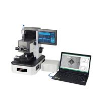
Micro Digital Hardness Tester / Testing Equipment With Lcd Large
Screen Display
Main interface display

Figure 3 main interface display diagram
| Control hardness: Displays the corresponding values for other
hardness units; | Test force: the test force loaded by the instrument; |
| D1 (D2): indentation diagonal length; | Charge time: test time, test force to maintain time; |
| Test temperature: Ambient temperature; | Number of tests: the number of shocks that have been completed when
measured; |
| Test field value: pre-set hardness value on the lower limit; | Average: multiple measurements to remove the average of the maximum
and minimum values; |
| Repeatability: The difference between the maximum and minimum
indentation averages. | |
2.3 Key definition
| OK | Confirmation key | ↑ | Direction and light source adjusting key |
| ESC | Return key | ↓ | Direction and light source adjusting key |
| CLR | Set zero key | ← | Direction and objective switch key |
| SET | Main menu key | → | Direction and objective switch key |
| DEL | Delete key | ↓ | Start key |
| PRT | Print key | DWL | Holding time select key |
3 Instrument installation
- Punch on the the prepared workbench,The specific dimensions are
shown in Figure 4;


Figure 4 working console
- Remove the outer box,take out Hardness tester mainframe and
accessories box;
- Take out the level adjustment screw from the accessory box,spin at
the bottom of the main body;
- Remove the cover,rotate the shockproof fastening screws(As shown in
Figure 4);
- Turn the test force change handwheel to 0.098N;
- Rotate the screws on the cover of the weight housing,remove the end
cap,take out the weight shaft and weight from the accessory box,set
the six weights on the weight axis from small to large.Wipe clean
weight shaft and weight before install;
- Grab the top of the weight shaft,place it in the weight housing,and
turn the weight axis,so that the cross pin is placed in the lever V
groove(As shown in Figure 5);
- Align the hole on the end cap with the weight axis,so that its
shoulder and weight box hole match,tighten two M3 screws;
- Turn test force change handwheel,so that the weight of the shell in
the positioning slot up and down flexible,cover the instrument
cover after all the above steps are completed;


Figure 5 internal structure diagram Figure 6 weight shaft
installation diagram
- Remove the dome cover,take out the micrometer from the accessory
box,inserted into the hole;
- Remove the cross case from the accessory box,use the gasoline to
clean the rust,lubricate with thin oil after being dried;
- Insert the cross test shaft into the hole of the lifting screw
rod,fasten with screws;
- Place the level gauge on the cross test stand,adjust the front and
rear horizontal screws,so that the bubble center.
 4 Operation and use
4.1 Preparation before use
The switch board is located on the right side of the
instrument,power switch, fuse holder and power socket on it.The
fuse in the fuse holder is 1A / 250V,used for electrical main
circuit,Remove the power cord from the accessory box Connected to
the power supply(As shown in Figure 7);
Press the "SET" key,the system pops up the system setup menu(As
shown in Figure 7),press "↓" "↑" to select the submenu of the
corresponding function, press "OK" to enter the setting menu, press
"ESC" to return to the previous menu;
Figure 8 system settings menu Figure 9 contrast hardness settings
submenu Figure 10 test the hardness settings submenu
Figure 11 Test Force Unit Selection Submenu Figure 12 Field Value
Setting Submenu Figure 13 Time and date settings submenu
Note: The user can set the sample according to the need to test the
hardness limit of the upper and lower limits to determine whether
the sample qualified.
Figure 14 Language Settings submenu Figure 15 Hold Time Setup Menu
Note: The user can set the time according to need, print test data
corresponding to the test time will be printed together.
- Press "DWL" key to pop up the load time setting menu(As shown in
Figure 14)."DEL" is used to delete the most recent test
record.Press the "PRT" key,the embedded printer on the hardness
tester prints all the current test records.
4.2 Operation steps
- Turn on the power switch,the main screen lights up,rotating test
force change handwheel,make the test force meet the selection
requirements,the force value of the load should be consistent with
the force displayed on the main screen,if the force value shows
inconsistency will lead to the calculation formula error and affect
the indication.Be careful to rotate the handwheel slowly,to avoid
the impact of excessive speed;
- The main screen is displayed(As shown in Figure 3),the zero must be
calibrated each time the power is turned on.Turn the drum,the
reticle of moving eyepiece,draw it closer,infinitely close to the
inside of the reticle,the inside of the two lines is in a critical
state without a gap(As shown in Figure 15),press the panel "CLR"
key,then the D1 on the main screen: the value is zero,that is zero
in the term.At this point, the bottom of the screen shows "waiting
for input D1", and the instrument enters the standby mode;
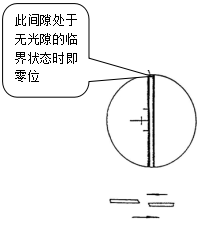

Figure 16 Critical state Figure 17 Knoop hardness
- Place the test piece or sample on the test bench,in the center of
the objective lens,Hardness meter automatically turn the 40x
objective lens in front of the sample (optical system magnification
of 400x, measurement state), if you want to observe the surface of
the larger field of view, you can switch 10x objective lens
(optical system magnification 100x , Observe the state), 40x
objective lens focal plane and 10x objective lens slightly
different, you can shake the lift hand wheel to make it clear;
- Swing lift screw hand wheel, so that the test bench to rise, when
the end of the objective lens and test pieces or samples away from
1 ~ 3mm, with micro-eyepiece observation, with the test bed slowly
rising, can be observed brightness gradually increased, Coming
soon, this time should slowly shake the hand wheel, until the
eyepiece observed in the test piece or sample surface of the clear
imaging;
- If the imaging observed in the eyepiece is blurred, turn the front
lens of the eyepiece (due to the difference in human vision) until
it is clear;
- If the plane imaging observed in the eyepiece has a partial bright
and dark condition, adjust the three adjustment screws on the light
source device so that the light source is in the center position.
If the field of view is too bright or too dark, press "↓"↑"Key, the
brightness will be transferred to a comfortable state;
- Rotate the differential cylinder to move the x-y platform to find
the preset position;
Note: If the hardness test, please 40x objective lens placed in
front of the main body, turn the lift hand wheel, so that imaging
clear. (The instrument components between the 40x objective lens
imaging as a benchmark test)
- Press the start button, the instrument automatically load, the top
right of the main screen shows "︾", after the end of the load into
the state, the top right of the main screen shows "=", while the
load time began to count down. The end of the countdown, automatic
unloading, the top right of the main screen shows "︽", after
unloading, 40x objective automatically switch to the front of the
main body, while the buzzer issued a "tick" sound, the end of the
test;
Note: If the sample surface uneven or composed of multiple faces,
should carefully switch the indenter and the objective lens, to
prevent the head touch the sample.
- The indentation in the eyepiece observation imaging, imaging is not
clear if the indentation rotary lifting hand wheel, making it
clear, as the indentation depth, the amplification of 400X, a small
influence is still the depth of focus plane;
- Turn right - hand wheel to make the reticle separately, moving left
eyepiece drum, so the left line move, the left medial and tangent
intersection shape when the indentation left the line, and then
move the right line, so that the inner shape and indentation
tangent intersection, press the button on the measuring eyepiece,
measuring the diagonal length of D1, rotating the eyepiece 90
degrees repeat the above steps, measuring the diagonal length of
D2, press the measurement button at the main screen shows the
measurement value and the conversion of hardness value, the end of
the first test;
- If the measurement is considered to be error, repeat the above
procedure again;
- The first test is completed before the second test, in accordance
with the requirements of the test procedures, the first test data
is not as a test result, so the second test hardness test as the
number of times in the test, this When the main screen status shows
the number of tests displayed: 1 times;
- If the indentation imaging is observed in the eyepiece (60% of the
eyepiece field of view as an effective field of view), the test
load should be reduced, otherwise the test results have some error,
if the indentation observed in the eyepiece is small , Can increase
the test load (must be within the allowable range, otherwise it may
breakdown the specimen) to improve the measurement accuracy;
- When measuring the Knoop hardness, only the length of d is measured
according to the requirements of the verification procedure. The
working mode and state are the same as the Vickers hardness
measurement,The screen is shown as Figure 16;
- The instrument can be equipped with micro-photographers; can test
the results of the material to shoot. When shooting, remove the
upper cover cover on the camera cover, the accessory box in the
camera interface screwed into the eyepiece seat thread;
- Remove the camera standard lens, the camera interface at the lens
hole, so that card reed bit;
- In the micrometer eyepiece to observe the surface, when the image
is clear, the main body on the left side of the camera measurement
conversion lever pulled out, then the optical path into the
shooting state;
- Observe the surface of the specimen in the eyepiece of the
photographer. If it is not clear, it can fine-tune the dioptric
adjustment ring or lift the screw to make the image clear.
- Press the shutter, shoot imaging surface;