
|
|
[China]

Trade Verify
Address: Building 36, Tianan Smart City, No. 228 Linghu Avenue, Xinwu District, Wuxi City, Jiangsu Province
Contact name:Wang

WUXI LEO TECHNOLOGY CO.,LTD |
|
Verified Suppliers
|

|
|
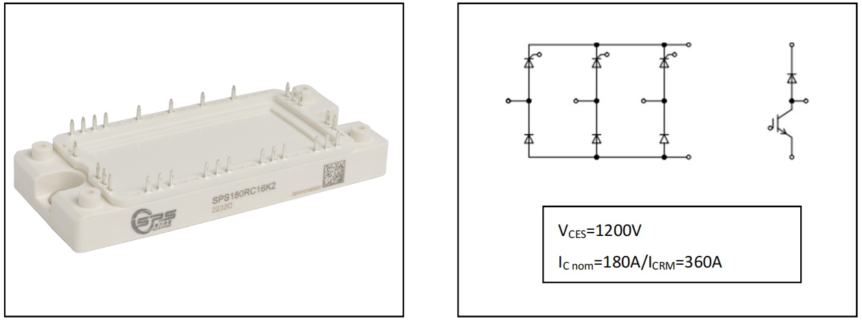
Solid Power-DS-SPS180RC16K2-S04040007 V1.0
Features:
Typical Applications:
Diode , Rectifier /
Maximum Rated Value /
|
Item |
Symbol |
Conditions |
Value |
Units |
|
反向重复峰值电压 Peak repetitive reverse voltage |
VRRM |
Tvj=25°C, IR=0.1mA |
1600 |
V |
|
最大正向均方根电流(每芯片) Maximum RMS forward current per chip |
IFRMSM |
TC=80°C, Tvj=150°C |
150 |
A |
|
最大整流器输出均方根电流 Maximum RMS current at rectifier output |
IRMSM |
TC=80°C |
180 |
A |
|
正向浪涌电流 Surge forward current |
IFSM |
tp=10ms, Tvj=25°C |
1300 |
A |
|
I2t-值 I²t-value |
I2t |
tp=10ms, Tvj=25°C |
8450 |
A2s |
|
Characteristic Values / 特征值 | ||||
|
Item |
Symbol |
Conditions |
Min. Typ. Max. |
Units |
|
正向电压 Forward voltage |
VF |
Tvj=25°C, IF=110A |
1.05 1.20 |
V |
|
阈值电压 Threshold voltage |
VTO |
Tvj=150°C |
0.80 |
V |
|
斜率电阻 Slope resistance |
rT |
Tvj=150°C |
2.40 |
mΩ |
|
反向电流
Reverse current |
IR |
Tvj=150°C, VR=1600V |
2 |
mA |
|
结-外壳热阻 Thermal resistance, junction to case |
RthJC |
Per diode / 每个二极管 |
0.28 |
K/W |
Thyristor-rectifier / 晶闸管,整流器
Maximum Rated Values /最大额定值
|
Item |
Symbol |
Conditions |
Value |
Units |
|
反向重复峰值电压 Peak repetitive reverse voltage |
VRRM |
Tvj=25°C |
1600 |
V |
|
最大正向均方根电流(每芯片) Maximum RMS forward current per chip |
IFRMSM |
TC=80°C |
150 |
A |
|
最大整流器输出均方根电流 Maximum RMS current at rectifier output |
IRMSM |
TC=80°C |
180 |
A |
|
正向浪涌电流 Surge forward current |
IFSM |
tp=10ms, Tvj=25°C tp=10ms, Tvj=130°C |
1800
1450 |
A A |
|
I²t -值 I²t-value |
I2t |
tp=10ms, Tvj=25°C tp=10ms, Tvj=130°C |
16200
10510 |
A2s A2s |
|
通态电流临界上升率 Critical rate of rise of on-state current |
(di/dt) cr |
Tvj = 130°C |
100 |
A/µs |
|
通态电压临界上升率 Critical rate of rise of on-state voltage |
(di/dt) cr |
Tvj = 130°C, VD=2/3VDRM |
1000 |
V/µs |
|
Characteristic Values / 特征值 | ||||
|
Item |
Symbol |
Conditions |
Min. Typ. Max. |
Units |
|
正向电压 Forward voltage |
VTM |
Tvj = 130 °C, IT = 110 A |
1.30 |
V |
|
阈值电压 Threshold voltage |
V(TO) |
Tvj=130°C |
0.90 |
V |
|
斜率电阻 Slope resistance |
rT |
Tvj=130°C |
3.20 |
mΩ |
|
门极触发电流 Gate trigger current |
IGT |
Tvj=25°C, VD=12V, RL=30Ω |
100 |
mA |
|
门极触发电压 Gate trigger voltage |
VGT |
Tvj=25°C, VD=6V |
2.00 |
V |
|
门极不触发电流 Gate non-trigger current |
IGD |
Tvj=130°C, VD=6V
Tvj=130°C, VD=0.5 VDRM |
6.0 3.0 |
mA mA |
|
门极不触发电压 Gate non-trigger voltage |
VGD |
Tvj=130°C, VD=VDRM |
0.25 |
V |
|
维持电流
Holding current |
IH |
Tvj=25°C, IT=1A |
250 |
mA |
|
擎住电流
Latching current |
IL |
Tvj=25°C, IG=1.2IGT |
300 |
mA |
|
门极控制延迟时间 Gate controlled delay time |
tgd |
DIN IEC 747-6 Tvj=25°C, iGM=0.6A, diG/dt=0.6A/µs |
1.2 |
µs |
|
换流关断时间 Circuit commutated turn-off time |
tq |
Tvj = 130°C, iTM = 50 A VRM = 100 V, VDM = 2/3 VDRM dVD/dt = 20 V/µs, -diT/dt = 10 A/µs |
150 |
µs |
|
反向电流
Reverse current |
IR ID |
Tvj=125°C, VR=1600V |
20 |
mA |
|
结-外壳热阻 Thermal resistance, junction to case |
RthJC |
Per Thyristor / 每个晶闸管 |
0.24 |
K/W |
|
IGBT Brake-Chopper / IGBT 制动-斩波器 Maximum Rated Values / 最大额定值
连续集电极直流电流 IC nom TC=80°C, Tvj=175°C 100 A | |||||
|
Continuous DC collector current IC TC=25°C, Tvj=175°C 140 A | |||||
|
开通延迟时间(电感负载) Turn-on delay time, inductive load |
td( on) Tvj=25°C 125 µs | ||||
|
上升时间(电感负载) Rise time, inductive load |
tr |
Tvj=25°C |
30 |
µs | |
|
关断延迟时间(电感负载) Turn-off delay time, inductive load |
td(off) |
IC=100A, VCE=600V VGE=±15V |
Tvj=25°C |
300 |
µs |
|
下降时间(电感负载) Fall time, inductive load |
tf |
RGon=1.5 Ω RGoff=1.5 Ω |
Tvj=25°C |
165 |
µs |
|
开通损耗能量(每脉冲) Turn-on energy loss per pulse |
Eon |
Tvj=25°C |
2.4 |
mJ | |
|
关断损耗能量(每脉冲) Turn-off energy loss per pulse |
Eoff |
Tvj=25°C |
7.5 |
mJ
A
K/W | |
|
短路数据 SC data |
ISC |
VGE≤15V, VCC=800V VCEmax=VCES-LsCE·di/dt, tp=10µs, Tvj=150°C |
360 | ||
|
结-外壳热阻 Thermal resistance, junction to case |
RthJC |
Per IGBT / 每个 IGBT |
0.25 | ||
|
Diode, Brake-Chopper / Maximum Rated Values / | |||||
|
反向恢复峰值电流
Peak reverse recovery current |
IRM Tvj=150°C 50 A | ||||
|
反向恢复时间 Reverse recovery time |
Trr |
IF=50A diF/dtoff=1300A/µs |
Tvj=150°C |
380 |
ns |
|
恢复电荷 Reverse recovery charge |
Qr |
VR = 600 V VGE=-15V |
Tvj=150°C |
8 |
µC |
|
反向恢复损耗(每脉冲) Reverse recovery energy (per pulse) |
Erec |
Tvj=150°C |
3.5 |
mJ
0.70 K/W | |
|
结-外壳热阻 Thermal resistance, junction to case |
RthJC |
Per diode / 每个二极管 | |||
![]()
|
Item |
Symbol |
Conditions |
Value |
Units |
|
绝缘测试电压 Isolation test voltage |
VISOL |
RMS, f=50Hz, t=1min |
2.5 |
kV |
|
模块基板材料 Material of module baseplate |
Cu | |||
|
内部绝缘 Internal isolation |
基本绝缘 (class 1, IEC 61140) Basic insulation (class 1, IEC 61140) |
Al2O3 | ||
|
爬电距离 Creepage distance |
端子-散热片 / terminal to heatsink 端子-端子/terminal to terminal |
10.0 |
mm | |
|
电气间隙 Clearance |
端子-散热片 / terminal to heatsink 端子-端子/terminal to terminal |
7.5 |
mm | |
|
相对电痕指数 Comperative tracking index |
CTI |
> 200 |
|
|
Item |
Symbol |
Conditions |
Min. |
Typ. |
Max. |
Units |
|
杂散电感,模块 Stray inductance module |
LsCE |
50 |
nH | |||
|
最大结温 Maximum junction temperature |
Tvj(max) |
逆变器, 制动-斩波器 /inverter, brake-chopper 整流器/rectifier |
175
125 |
°C °C | ||
|
在开关状态下温度 Temperature under switching conditions |
Tvj(op) |
逆变器, 制动-斩波器 /inverter, brake-chopper 整流器/rectifier |
-40
-40 |
150
125 |
°C °C | |
|
储存温度
Storage temperature |
Tstg |
-40 |
125 |
°C | ||
|
模块安装的安装扭距 Mounting torque for module mounting |
M |
3.00 |
6.00 |
Nm | ||
|
重量
Weight |
G |
180 |
g |
IGBT
Output characteristic IGBT, Brake-Chopper(typical) IC=f(VCE) Forward characteristic of Diode, Brake-Chopper(typical)
VGE=15V IF=f(VF)

Forward characteristic of Diode, Rectifier (typical)
IF=f(VF)
![]()

Circuit diagram headline

Package outlines


