
|
|
[China]

Trade Verify
Address: Block V5, Ronghao Industrial Town, Gaoling District, Xi'an City, Shaanxi Province
Contact name:Gao

Xi 'an West Control Internet Of Things Technology Co., Ltd. |
|
Verified Suppliers
|
|
|
NYRD703 ( Stainless Steel )1.8GHz Guided Wave Radar Level Meter
The guided wave radar level meter is a level meter based on the principle of time domain reflection (TDR). The electromagnetic pulse of the radar level gauge propagates along the steel cable or probe at the speed of light. Part of the pulse of the level meter is reflected to form an echo and return to the pulse transmitter along the same path. The distance between the transmitter and the surface of the measured medium is proportional to the propagation time of the pulse during that period, and the liquid level height is calculated.
Radar Level Meter Technical Parameter
| Parameters | Frequency: 100MHZ-1.8GHZ Measuring range:-cable :0-30m; rod, coaxial :0-6m Repeatability: ± 3mm Resolution: 1mm Sampling: echo 55 samples / s Response speed: 0.2S (depending on the actual usage) Output current signal :4-20mA Accuracy: <0.1% |
| Communication Interface | HART communication protocol |
| Process connection | G1-1/2 Flange DN50, DN80, DN100, DN150 |
| Process pressure | -1 ~ 40bar |
| Power | Power: 24VDC (± 10%), ripple voltage: 1Vpp Power consumption: max 22.5mA |
| Environmental conditions | temperature -40 ℃ ~ +80 ℃ |
| Housing protection grade | IP68 |
| Explosion levels | EXiaIICT6 |
| Instrumentation power supply and signal output wire connection | Sharing a two-core shielded cable Cable entry: 2 M20 × 1.5 (the cables diameter of 5 - 9mm) |
※ Note: Products can be customized according to the specific requirements of users!
Radar Level Meter Operating Principle
Guided Wave Radar is the kind of measuring instrument that is based on the principle of time travel. The radar wave travels at the speed of light, and its running time can be converted into a level signal by the electronic components. The probe emits high-frequency pulses which spread along the cable, and the pulses are reflected back when they encounter the material surface and received by the receiver inside the meter. The distance signal is then converted to the level signal.
Input
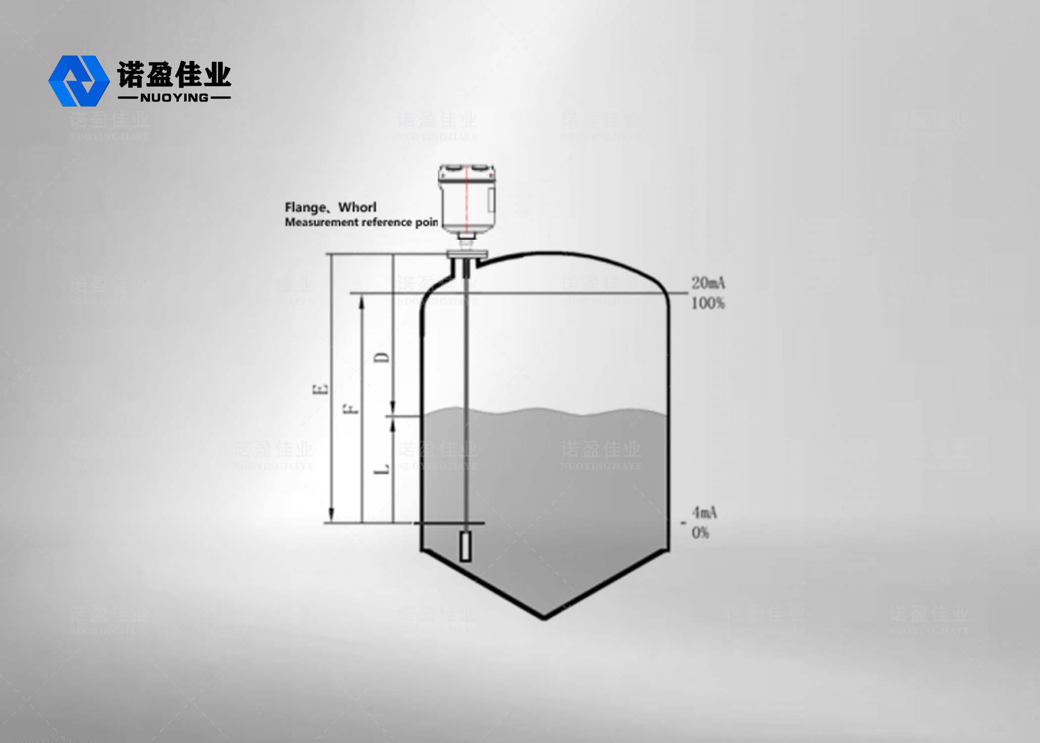
The reflected pulse signal is conducted along the cable back to the electronic circuit of the meter, and the microprocessor processes this signal to identify the echo produced by the microwave pulses at the material surface. The recognition of the correct echo signal is done by the intelligent software. The distance D to the material surface is proportional to the time travel T of the pulse:
D=C×T/2
where C is the speed of light
As the distance E of the empty tank is known, the level L is:
L=E-D
Output
Set accordingly to the empty tank height E (= the zero point), the full tank height F (= the full scale) and some application parameters. The application parameters will automatically make the instrument adapt to the measurement environment, corresponding to the output of 4 ~ 20mA.
Radar Level Meter Installation requirements
Measurement Range

Symbol explanation:
H---- Measurement range
L---- Empty tank distance
B---- The blind area at the top
E---- The minimum distance between the probe and the tank wall
The blind area refers to the minimum distance between the highest level of the material surface and the measurement reference point.
The bottom blind area refers to the distance near the cable bottom that cannot be precisely measured.
The effective distance is the one between the top blind area and the bottom blind area.
Note:Only when the material level is at between the top and bottom blind areas can a reliable measurement of the material level be guaranteed.
Installation Guide
The following installation guide is suitable for that of cable and rod probes for measurement of solid particles and liquid. The coaxial tubular probe is applied only to the liquid object.

Installation position:
Try to stay away from the outlet and inlet.
The meter should not touch the tank internal wall for metal tanks and plastic tanks. If it is a metal tank, the material level meter should not be installed at the center of the tank.
It is proposed to install at 1/4 of the silo diameter.
Probes of cable or rod types should keep a distance away from the tank wall not less than 30cm.
The probe bottom should be about 30mm to the tank bottom.
The probe should keep a distance not less than 200mm from the obstacles within the tank.
The sensor can be installed at the center of the tank top, if the bottom of the container is a cone, so the measurement can be taken to the tank bottom.
The picture on the right shows the rod-type radar installation diagram, mainly used for liquid level measurement.


