

Active Member
|
[China]

Address: Room1301, Building 11, yard 88 , Sanluju Road, Fengtai District, Beijing, China
Contact name:

Beijing Tianyihongda Science & Technology Development Co., LTD |
|
|
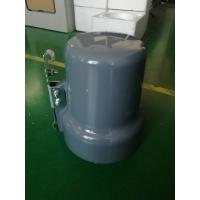
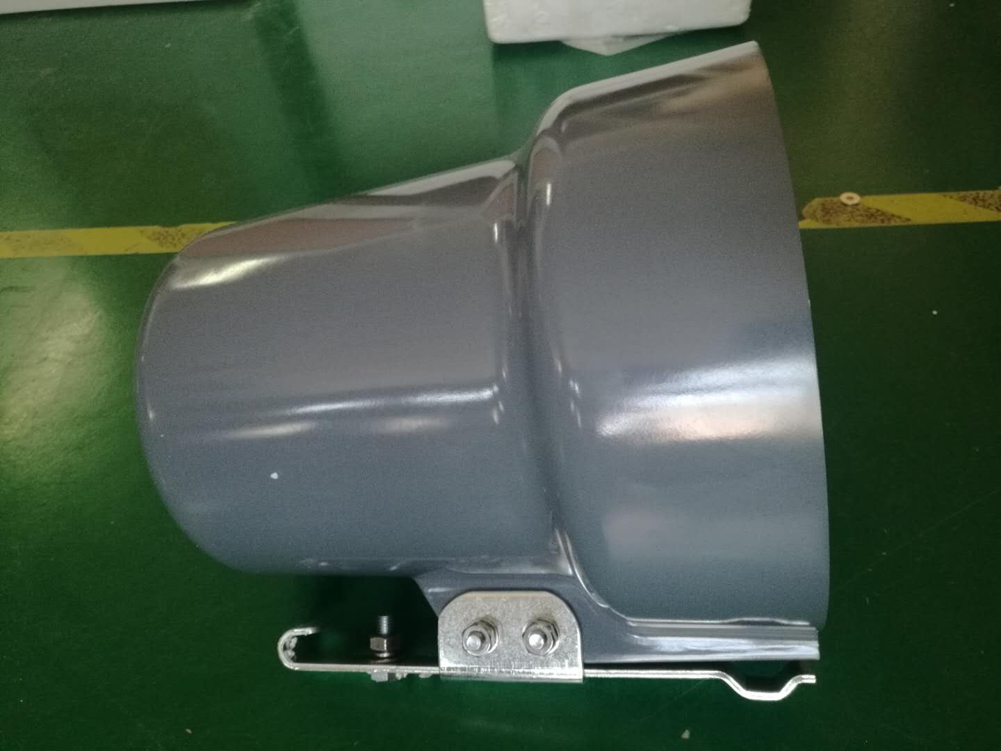
Wireless transmission and remote control power distribution terminal connecting circuit breaker on pole
This is a new HV switch control device equipped with both the imported DSP high-speed sampling chips and the high-performance ARM chips, and can fast and stably finish the monitoring on the switch. It boasts of such functions as the protection, measuring, controlling, monitoring, communication, remote control and so on and features high integration level, flexible configuration and user-friendly interface, widely applied to the radiant and ring network power supply systems to help the systems identify transient and permanent line faults, eliminate the impact of transient line faults automatically, isolate the permanent fault segments to avoid prolonged power failure in large area, and automatically recover the power supply in fault-free areas, so as to realize the automation of power distribution network in a economical and practical way.
Operating ambient temperature: From -40℃ to +85℃.
Relative air humidity: The air humidity can not exceed 50% at the maximum temperature and higher air humidity is allowed at lower temperature. For example, the air humidity shall be 90% at +20℃ as it may occasionally cause condensation with the temperature chan
ges.Atmospheric pressure: 66kPa~108kPa.
Operating environment: no explosive and flammable materials, no air or conductive dust which will damage the insulation and cause metal corrosion, no serious mold and no severe vibration sources, with measures to defend against rain, snow, wind, sand, dust and static electricity.
Table for Selection of Fixed Values for Zero-sequence Protection Current
| Length of cable at switch load side (m) | 50 | 100 | 150 | 200 | 250 | 300 | 350 | 400 | 450 | |
| Length of overhead line at switch load side (m) | <1000 | <4000 | ||||||||
| Fixed value (A) | 0.2 | 0.4 | 0.6 | 0.8 | 1.0 | 1.2 | 1.4 | 1.6 | 1.8 | 2.0 |
| Length of cable at switch load side (m) | 480 | 500 | 550 | 600 | 650 | 700 | 750 | 800 | 850 | 900 |
| Fixed value (A) | 2.2 | 2.4 | 2.6 | 2.8 | 3.0 | 3.2 | 3.4 | 3.6 | 3.8 | 4.0 |
Calculation formula for fixed values: Fixed value of current =1.5×3×(S1×L1+S2×L2)
L1 is the total length of overhead line at boundary switch load side. S1 is the empirical value of capacitive current of overhead line per km per phase. The recommended value is 0.02A/km.
L2 is the total length of cable at boundary switch load side. S2 is the empirical value of capacitive current of cable per km per phase. The recommended value is 1A/km.
Selection of Fixed Values for Zero-sequence Protection Delay
Choose 1S when the neutral point is not earthed or earthed by arc suppression coil. Choose OS or lower when the neutral point is earthed by low resistance.
The calculation of fixed values for zero-sequence protection current only depends on the direct earth capacitance of cable or overhead line at switch load side. The table above is the results of approximate amount multiplied by safety factor. Users can calculate personally according to the actual condition of the line at switch load side. If there are both cable and overhead line at switch load side, add their direct earth capacitances together. The safety factor shall be chosen between 1.5~3 (It is recommended that a larger safety factor shall be chosen when the fixed value is relatively small, while a smaller one shall be chosen when the fixed value is relatively large.)
Type Test Items
1. appearance and structure 2.function 3. electrical device
performance 4.low temperature performance 5.high temperature
performance 6.alternating temperature humidity7.vibrationendurance
8.incline drop test 9. electrical device life 10. static
electricity and elecro-discharge immunity test 11.radio frequency
electromagnetic field radiated immunity test 12.surge impact
immunity test 13. power frequency magnetic field immunity test. 14.
Adjacent interference test 15.short-circuit withstand impact test
16. fire hazard test 17. power consumption test 18. protection
grade test 19. gripping strength test of grip structure.


