
|
|
[China]

Trade Verify
Contact name:Daisy He

Shanghai Genius Industrial Co., Ltd |
|
Verified Suppliers
|
|
|
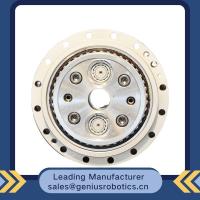
Harmonic Gearbox Drive Servo Drive Component Sets for Robot Motion Control
The harmonic drive based on metal elasticity consists of
only three basic components (wave generator. flexible wheel and
rigid wheel),(because of the different shapes,some of them are
composed of four basic components,but the driving principleremains
unchanged)
Wave aenerator:elliptical cam with a thin ball bearina
embedded in the periphery. The inner wheel of the
bearing is fixed on the cam. and the outer ship realizes the
elastic deformation through the ball. Usually
mounted on the input shaft
Flexible wheel:thin-walled metal elastomer parts. The
outer part of the opening is provided with a gear and is usually
mounted on the output shaft.
Rigid wheel:rigid annular parts.The inside is engraved
with gears,the number of gears is two more than flexible wheel's
usuallv fixed on the shell
Since the flexible wheel will undergo elastic
deformation repeatedly, the transmission torque of harmonic drive
is determined based on the fatigue strength of the flexible gear
bottom.
The values of rated torque and allowable peak torque at
start and stop are all within the fatigue limit of flexible gear
bottom.
The value of instantaneous allowable maximum torque(impact
torque)is the limit value within the fatigue limit of the soft gear
bottom. and the fatique failure may occur when the instantaneous
allowable maximum torque is exceeded frequently.Therefore,in order
to avoid fatigue failure,the number of impact torque should be
limited
Model | Speed ratio | Enter the rated torque at 2000r/min | Allowed peak torque at start stop | The allowable maximum of the average load torque | |||
Nm | kgfm | Nm | kgfm | Nm | kgfm | ||
11 | 80 | 3.8 | 0.4 | 8.5 | 0.9 | 6.8 | 0.7 |
100 | 4.1 | 0.4 | 8.9 | 0.9 | 7.2 | 0.7 | |
14 | 50 | 6.2 | 0.6 | 20.7 | 2.1 | 7.9 | 0.7 |
80 | 9 | 0.9 | 27 | 2.7 | 12.7 | 1.3 | |
100 | 9 | 0.9 | 32 | 3.3 | 12.7 | 1.3 | |
17 | 50 | 18.4 | 1.9 | 39 | 4 | 29.9 | 3 |
80 | 25.3 | 2.6 | 49.5 | 5 | 31 | 3.2 | |
100 | 27.6 | 2.8 | 62 | 6.3 | 45 | 4.6 | |
20 | 50 | 28.8 | 2.9 | 64.4 | 6.6 | 39 | 4 |
80 | 39.1 | 4 | 85 | 8.8 | 54 | 5.5 | |
100 | 46 | 4.7 | 94.3 | 9.6 | 56 | 5.8 | |
120 | 46 | 4.7 | 100 | 10.2 | 56 | 5.8 | |
160 | 46 | 4.7 | 112 | 10.9 | 56 | 5.8 | |
25 | 50 | 44.9 | 4.6 | 113 | 11.5 | 63 | 6.5 |
80 | 72.5 | 7.4 | 158 | 16.1 | 100 | 10.2 | |
100 | 77.1 | 7.9 | 181 | 18.4 | 124 | 12.7 | |
120 | 77.1 | 7.9 | 192 | 19.6 | 124 | 12.7 | |
32 | 50 | 87.4 | 8.9 | 248 | 25.3 | 124 | 12.7 |
80 | 135.7 | 13.8 | 350 | 35.6 | 192 | 19.6 | |
100 | 157.6 | 16.1 | 383 | 39.1 | 248 | 25.3 | |
120 | 157.6 | 16.1 | 406 | 41.4 | 248 | 25.3 | |
FAQ
Q: What should I provide when I choose gearbox/speed reducer?
A: The best way is to provide the motor drawing with parameter. Our engineer will check and recommend the most suitable gearbox model for your refer.
Or you can also provide below specification as well:
1) Type, model and torque.
2) Ratio or output speed
3) Working condition and connection method
4) Quality and installed machine name
5) Input mode and input speed
6) Motor brand model or flange and motor shaft size


