

Active Member
|
[China]

Address: Building #B1, Wuhan Future City, East Lake High-tech Zone, Wuhan 430206, China
Contact name:Rebecca

Wuhan ETERN Optoelectronics Technology Co.,Ltd. |
|
|
ETERN 100GHz/200GHz CWDM 3-port TFF devices are available on ITU
channel spacing of 100GHz/200GHz CWDM spacing. These thin film
filter products utilize hermetic and epoxy-free optical path
technology to provide excellent performance and reliability.
Features
1. Flat and Wide Passband
2. High Stability and Reliability
3. Low Insertion Loss, High Isolation
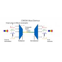
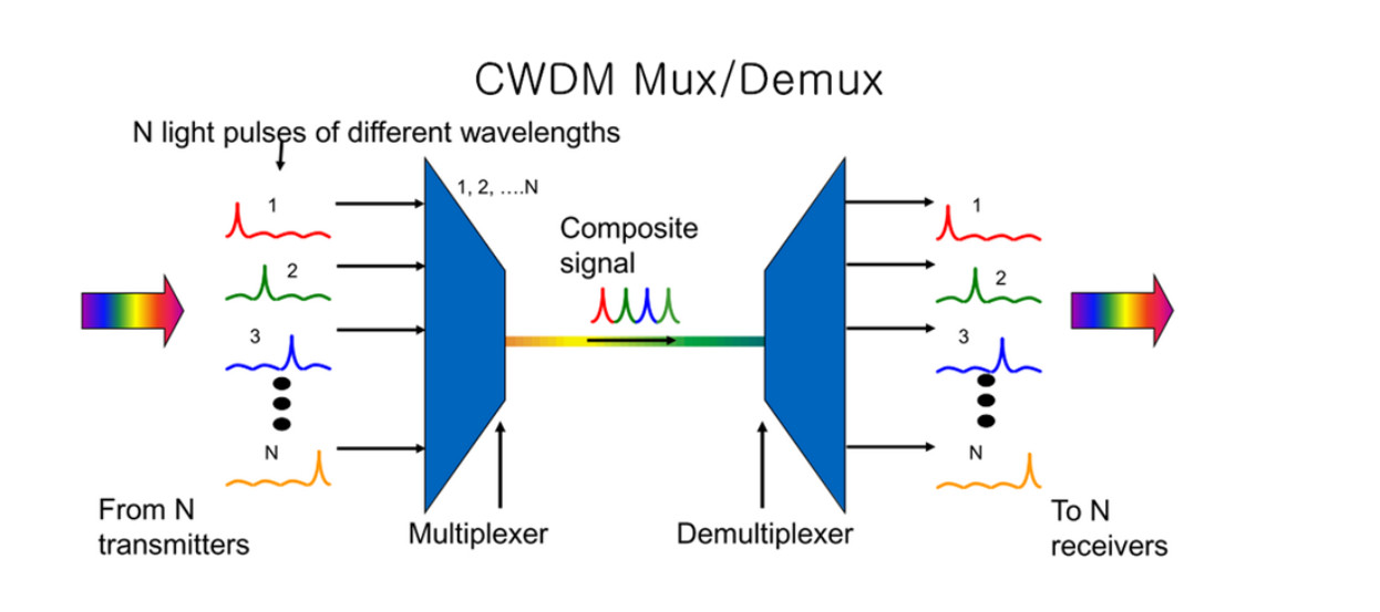
Coarse wavelength division multiplexing (CWDM) is a wavelength
division multiplexing (WDM) technology that combines multiple
signals at various wavelengths for simultaneous transmission over
fiber cables. This passive technology allows for any protocol to be
transported over the link.
CWDM is a low-cost method to maximize existing fiber by decreasing
the channel spacing between wavelengths. CWDM has a lower cost per
channel than dense WDM (DWDM) and no configuration is necessary.
CWDM optical devices can increase bandwidth on existing fiber
infrastructure and alleviate fiber exhaustion.
Our CWDM solutions support these different channel variations as
well as add/drop modules. Our CWDM module is also available in a
hardened temperature grade for our 16-channel mux/demux to provide
the right solution for your network.
Performance Specification
| Parameter | Units | Value | ||
| Channels | GHz | 100/200/300 | ||
| Central Wavelength | nm | ITU-T Grid | ||
| Pass band Flatness | dB | ≤0.5 | ||
| Typ. | 0.7 | |||
| Insertion Loss | dB | |||
| Max. | 0.8 | |||
| Polarization Dependent Loss (PDL) | dB | ≤0.15 | ||
| Adjacent Channel Isolation | dB | ≥25/≥25/≥30 | ||
| Non-Adjacent Channel Isolation | dB | ≥45 | ||
| Return Loss | dB | ≥45 | ||
| Polarization Mode Dispersion(PMD) | ps | ≤0.15 | ||
| Directivity | dB | ≥50 | ||
| Operating Temperature | ℃ | -5 to +70 | ||
| Storage Temperature | ℃ | -40 to +85 | ||
Notes: 1. Measured with connectors; IL will be 0.3dB
worse and RL will be 5dB lower with connectors.
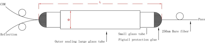
Mechanical Dimensions(Unit:mm)
Ordering Information
| WDM - | □ | □□- | □ | □□ | □ |
| Spacing | Channel | Fiber Type | Fiber Length | Connector | |
| WDM | 1=100GHz | C21=C21 | 1=250um SM | 00=Adapter | 1=None |
| 2=200GHz | C22=C22 | 2=900um SM | 05=0.5m | 2=FC/UPC | |
| C=CWDM | XX=1XX1 | 3=2.0mm SM | 10=1.0m | 3=FC/APC | |
| ...... | 4=3.0mm SM | 15=1.5m | 4=LC/UPC | ||
| 20=2.0m | 5=LC/APC | ||||
| ...... | 6=SC/UPC | ||||
| 7=SC/APC | |||||
| X=Special | |||||


