

Active Member
|
[China]

Address: No.337,Kaichuang Road,Baitawang Industrial Distrit, Beibaixiang Town,Yueqing City,Zhejiang Province,China
Contact name:

Wenzhou Ginri Power Automation Co., Ltd. |
|
|
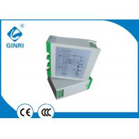
50/60 Hz Three Phase Voltage Monitoring Relay Unbalance 1 C/O Output
Three-phase imbalance: It means that the three-phase current (or voltage) amplitude is inconsistent in the power system, and the amplitude difference exceeds the specified range.
The solution to the three-phase imbalance of the power grid caused
by an asymmetric load:
1 . Distribute asymmetrical loads at different power supply points
to reduce the problem of excessively unbalanced degrees caused by
concentrated connections.
2 . Use cross-equalization to distribute asymmetrical loads to each
phase as much as possible to balance them.
3 . Increase the short-circuit capacity of the load access point,
such as changing the network or increasing the power supply voltage
level to improve the system's ability to withstand unbalanced
loads.
4 , install the balance device. Listed briefly above are
several technical measures to solve the hazards of three-phase
voltage or current imbalance on the power grid and power quality.
Which specific measures should be adopted is more reasonable and
effective, and it must be determined after implementation of
technical and economic comparisons based on actual conditions.
In the low-voltage three-phase four-wire system for urban residents
and rural power supply systems: As the power consumers are mostly
single-phase loads or single-phase and three-phase loads are mixed,
and the load size is different and the power consumption time is
different. Therefore, the unbalanced current between the three
phases in the power grid is objectively existent, and this kind of
power imbalance situation has no regularity and cannot be foreseen
in advance. This leads to a long-term imbalance in the three-phase
load of the low-voltage power supply system. For three-phase
unbalanced currents, the power sector has few effective solutions
other than to distribute the load as much as possible.
♦ Features
-- Three-phase monitoring of phase loss, over- and undervoltage and phase unbalance
-- Powered by the measuring circuit
-- 1 C/O contact
-- 4 LEDs for status indication
♦ Protective Functions
-- Phase loss
-- Overvoltage
-- Undervoltage
-- Phase unbalance
♦ Typical Applications
• Pumps • Fans
• Blowers • Motors
• Compressors
♦ Approvals
• CE • CCC
♦ Technical data
| Type | JVR-382 |
| Measuring circuit | L1,L2,L3 |
| Rated voltage | 220VAC,380VAC ,440VAC 460VAV,480VAC,50/60Hz |
| Monitoring functions | phase loss, overvolatege, undervoltage, phase unbalance |
| Voltage setting range | Type suffix overvoltage undervoltage blank +15% -15% A +10% -10% B +12.5% -10% C +15% -12.5% T Customized Customized |
| Indicators | phase loss, overvolatege, undervoltage, and normal |
| Output contacts | 1 C/O |
| Contact capacity | 3A ,250VAC |
| Dimensions (H x W x D) | 68×30×76mm |
| Mounting | DIN rail |


