
|
|
[China]

Trade Verify
Address: Foor 2, 4th Buidling, A Zone, Xinhe Xinxing Industrial 3th Zone, Fuhai Avenue, Baoan, Guangdong, China.
Contact name:Catlin Zeng

Shenzhen Wofly Technology Co., Ltd. |
|
Verified Suppliers
|
|
|

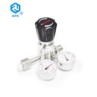
Features
1. Single stage piston sensing structure
2. Larger outlet pressure adjustment range
3. It can be used for standard gas and non corrosive gas
4. Install a 20 micron filter element at the inlet
5. Oxygen environment application options can be provided

Technical Data
1. Maximum inlet pressure: 4500psi or 6000PSI
2. Outlet pressure range: 0 ~ 1500,0 ~ 3000
3. Material of internal components:
Valve seat: PCTFE
Piston: 316L O-ring: FKM
Filter element: 316L
4. Working temperature: - 26 ℃ ~ + 74 ℃ (- 15 ℉ ~ + 165 ℉)
5. Leakage rate (helium):
Inside: no visible bubbles
External: no visible bubbles
6. Flow coefficient (CV): 0.09
7. Parent port:
Inlet: 1 / 4NPT
Outlet: 1 / 4NPT
Pressure gauge port: 1 / 4NPT


Ordering Information
| R41 | L | B | B | D | G | 00 | 00 | P |
| Item | Body Materia | Body Hole | Inlet Pressure | Outlet Pressure | Pressure Gauge | Inlet Size | Outlet Size | Options |
| R41 | L:316 | A | B:6000psig | D:0~3000psig | G:MPa gauge | 00:1/4″NPT(F) | 00:1/4″NPT(F) | P:Panel mounting |
| B:Brass | B | D:3000psig | E:0~1500psig | P:Psig/bar gauge | 00:1/4″NPT(M) | 00:1/4″NPT(M) | ||
| D | F:0~500psig | W:No gauge | 10:1/8″OD | 10:1/8″OD | ||||
| G | G:0~250psig | 11:1/4″OD | 11:1/4″OD | |||||
| J | 12:3/8″OD | 12:3/8″OD | ||||||
| M | 15:6mm”OD | 15:6mm”OD | ||||||
| 16:8mm”OD | 16:8mm”OD |
Installation instructions and precautions of pressure reducing valve
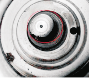 |  |  |
| 1.Before installing the pressure reducing valve, the pipeline must be cleaned, and the gas should be used for continuous purging to thoroughly clear the magazines and particles such as iron filings when cutting the pipeline; | 2.The filter must be installed upstream of the pressure reducing valve, otherwise the system particles will damage the valve seat,resulting in internal leakage of the pressure regulator, downstream pressure rise, and easy damage to the outlet pressure gauge or other equipment. It is recommended to use a filter element with a precision of not less than 20 microns | 3.It is not recommended to use thread sealant or liquid raw material tape for NPT thread installation. Improper operation will easily cause liquid to flow to the filter element in the valve and cause the filter element to be blocked. Finally, there is no pressure at the valve outlet or the flow is too low |
4.In the flow state, turn the handle clockwise to increase the
outlet pressure and counterclockwise to decrease the outlet
pressure. When the outlet pressure is reduced to zero, the handle
of the pressure reducing valve should be in a loose state.
Excessive counterclockwise rotation of the handle may cause the
thread to get stuck, or the handle is loose and cannot be adjusted
again
5.It is not recommended to use the pressure reducing valve as a
stop valve for a long time, otherwise the valve seat may be
deformed, resulting in unstable flow
6.Handle with care to avoid any impact, especially the pressure
reducing valve with pressure gauge. The pressure gauge is a
sensitive element and may be damaged by external force
Project Case
purpose
Semiconductor factory, liquid crystal factory, organic EL factory,
compound factory, solar cell factory
Basic composition
Special gas, gas supply equipment, distribution box, purification
equipment, waste gas treatment equipment, detector, monitoring
equipment


