
|
|
[China]

Trade Verify
Address: 4/F, 2-3 Building, Tongfuyu Industrial Zone, Aiqun Rd, Shiyan, Baoan District, Shenzhen, China
Contact name:Evelyn

Shenzhen iseelink Communication Technology Co., Ltd. |
|
Verified Suppliers
|
|
|
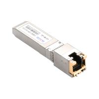
30-meter 10G based industrial Copper Transceiver
Application
Description
Dimension

Part No. | Data Rate(Mbps) | Reach(km) | Temperature |
OST01 | 10/100/1000Mbps, with SGMII interface, enable the auto-negotiation default, support Rx_LOS as link indication function, | 0.1 | -40℃~85℃ |
OST01N | 10/100/1000Mbps, with SGMII interface, enable the auto-negotiation default, does not have a link indication feature (RX_LOS is internally grounded) | 0.1 | -40℃~85℃ |
SFP to Host Connector Pin Out
| Pin | Signal name | Description | MSA Notes |
| 1 | VEET | Transmitter ground (common with receiver ground) | |
| 2 | TFAULT | Transmitter Fault. Not supported | Note 1 |
| 3 | TDIS | Transmitter Disable. PHY disabled on high or open | Note 2 |
| 4 | MOD_DEF(2) | Module Definition 2. Data line for Serial ID. | Note 3 |
| 5 | MOD_DEF(1) | Module Definition 1. Clock line for Serial ID. | Note 3 |
| 6 | MOD_DEF(0) | Module Definition 0. Grounded within the module. | Note 3 |
| 7 | Rate Select | No connection required | |
| 8 | LOS | Loss of Signal - High Indicates Loss of Signal | |
| 9 | VEER | Receiver Ground (common with transmitter ground) | |
| 10 | VEER | Receiver Ground (common with transmitter ground) | |
| 11 | VEER | Receiver Ground(common with transmitter ground) | |
| 12 | RD- | Receiver Inverted DATA out. AC Coupled | Note 5 |
| 13 | RD+ | Receiver Non-inverted DATA out. AC Coupled | Note 5 |
| 14 | VEER | Receiver Ground (common with transmitter ground) | |
| 15 | VCCR | Receiver Power Supply | Note 6 |
| 16 | VCCT | Transmitter Power Supply | Note 6 |
| 17 | VEET | Transmitter Ground (Common with Receiver Ground) | |
| 18 | TD+ | Transmitter Non-Inverted DATA in. AC Coupled. | Note 7 |
| 19 | TD- | Transmitter Inverted DATA in. AC Coupled. | Note 7 |
| 20 | VEET | Transmitter Ground(common with receiver ground) |
1. TX Fault is not used and is always tied to ground through a 100 ohm resistor.
2. TX Disable as described in the MSA is not applicable to the 1000BASE-T module, but is used for convenience as an input to reset the internal ASIC. This pin is pulled up within the module with a 4.7 KW resistor.
Low (0 – 0.8 V): Transceiver on
Between (0.8 V and 2.0 V): Undefined
High (2.0 – 3.465 V): Transceiver in reset state
Open: Transceiver in reset state
3. Mod-Def 0,1,2. These are the module definition pins. They should be pulled up with a 4.7-10 KW resistor on the host board to a supply less than VCCT + 0.3 V or VCCR + 0.3 V.
Mod Def 0 is tied to ground through a 100 ohm resistor to indicate that the module is present.
Mod-Def 1 is clock line of two wire serial interface for optional serial ID
Mod-Def 2 is data line of two wire serial interface for optional serial ID
4. RD-/+: These are the differential receiver outputs. They are ac coupled 100 ohm differential lines which should be terminated with 100 ohm differential at the user SerDes. The ac coupling is done inside the module and is thus not required on the host board. The voltage swing on these lines will be between 370 and 2000 mV differential (185 – 1000 mV single ended) when properly terminated. These levels are compatible with CML and LVPECL voltage swings.
5. VCCR and VCCT are the receiver and transmitter power supplies. They are defined as 3.3 V ± 5% at the SFP connector pin. The maximum supply current is about 300mA and the associated in-rush current will typically be no more than 30 mA above steady state after 500 nanoseconds.
6. TD-/+: These are the differential transmitter inputs. They are ac coupled differential lines with 100 W differential termination inside the module. The ac coupling is done inside the module and is thus not required on the host board. The inputs will accept differential swings of 500 – 2400 mV (250 –1200 mV single ended), though it is recommended that values between 500 and 1200 mV differential (250 – 600 mV single ended) be used for best EMI performance. These levels are compatible with CML and LVPECL voltage swings.

Feature
Specification
| Pin | Signal name | Description | MSA Notes |
| 1 | VEET | Transmitter ground (common with receiver ground) | |
| 2 | TFAULT | Transmitter Fault. Not supported | Note 1 |
| 3 | TDIS | Transmitter Disable. PHY disabled on high or open | Note 2 |
| 4 | MOD_DEF(2) | Module Definition 2. Data line for Serial ID. | Note 3 |
| 5 | MOD_DEF(1) | Module Definition 1. Clock line for Serial ID. | Note 3 |
| 6 | MOD_DEF(0) | Module Definition 0. Grounded within the module. | Note 3 |
| 7 | Rate Select | No connection required | |
| 8 | LOS | Loss of Signal - High Indicates Loss of Signal | |
| 9 | VEER | Receiver Ground (common with transmitter ground) | |
| 10 | VEER | Receiver Ground (common with transmitter ground) | |
| 11 | VEER | Receiver Ground(common with transmitter ground) | |
| 12 | RD- | Receiver Inverted DATA out. AC Coupled | Note 5 |
| 13 | RD+ | Receiver Non-inverted DATA out. AC Coupled | Note 5 |
| 14 | VEER | Receiver Ground (common with transmitter ground) | |
| 15 | VCCR | Receiver Power Supply | Note 6 |
| 16 | VCCT | Transmitter Power Supply | Note 6 |
| 17 | VEET | Transmitter Ground (Common with Receiver Ground) | |
| 18 | TD+ | Transmitter Non-Inverted DATA in. AC Coupled. | Note 7 |
| 19 | TD- | Transmitter Inverted DATA in. AC Coupled. | Note 7 |
| 20 | VEET | Transmitter Ground(common with receiver ground) |


