
|
|
[China]

Trade Verify
Address: 4/F, 2-3 Building, Tongfuyu Industrial Zone, Aiqun Rd, Shiyan, Baoan District, Shenzhen, China
Contact name:Evelyn

Shenzhen iseelink Communication Technology Co., Ltd. |
|
Verified Suppliers
|
|
|
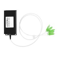
OSW1×N TTL optical fiber switch
Introduction of OSW 1*N optical fiber switch
Optical switch is a kind of functional component, with the ability of switching optical route. In optical fiber transmission system, it is used for multi-channel fiber monitoring, multi light source/ detector selection, and optical fiber path protection etc. They have the characteristics of small size, fast response speed and stable performance, and can be widely used in various optical communication and testing systems.
Applications of optical fiber switch
Specifications
| Parameters | Unit | OSW1×N | |||
| Insertion Loss | dB | 1 < N ≤ 32 | 32 < N ≤ 64 | 64 < N ≤ 128 | |
| Type: 0.8 Max: 1.0 | Type: 0.8 Max: 1.2 | Type: 0.8 Max: 1.3 | |||
| Wavelength Range | nm | 850±40 / 1300±40,1550 MM | 1260 ~ 1650 SM | ||
| Test Wavelength | nm | 850 / 1300,1550 MM | 1310 / 1550 SM | ||
| Return Loss | dB | MM ≥ 30 SM ≥ 50 | |||
| Crosstalk | dB | ≥ 70 | |||
| PDL | dB | ≤ 0.05 | |||
| WDL | dB | ≤ 0.25 | |||
| TDL | dB | ≤ 0.25 | |||
| ER (PM swtich) | dB | ≥ 16 (PoIarization Maintaining switch) | |||
| Repeatability | dB | ≤ ±0.05 | |||
| Durability | Cycles | ≥ 10 Million | |||
| Switching Time | ms | ≤ 10(Sequence switch time of adjacent channel) | |||
| Optical Power | mW | ≤500 | |||
| Operating Temperature | ℃ | -5 ~ +70 | |||
| Storage Temperature | ℃ | -40 ~ +85 | |||
| Relative Humidity | % | 5 ~ 95 | |||
| Dimension | mm | 135×40×32 (N≤12) | 135×60×32(N≤18) | 135×60×38 (N≤32) | |
| 150×80×67 (N≤64) | 165×100×100 (N≤98) | 185×130×130 (N≤128) | |||
Pin Configurations
DB-9 male connector (max.1×16)
| Pin No. | Signal Name | I / O | Description |
| 1 | D0 | Input | TTL, Channel selection bit 0 |
| 2 | D1 | Input | TTL, Channel selection bit 1 |
| 3 | D2 | Input | TTL, Channel selection bit 2 |
| 4 | D3 | Input | TTL, Channel selection bit 3 |
| 5 | /RESET | Input | TTL, Low level reset to channel 0. High level means channel selection bits are effective. |
| 6 | /READY | Output | TTL, Ready (High=Not ready, Low=Ready) |
| 7 | ERROR | Output | TTL, Error (High=Error, Low=No error) |
| 8 | GND | Input | Ground |
| 9 | +5VDC | Input | 5.0±5% VDC Power Supply (max 800mA) |
DB-15 male connector (max.1×32)
| Pin No. | Signal Name | I / O | Description |
| 2 | D0 | Input | TTL, Channel selection bit 0 |
| 3 | D1 | Input | TTL, Channel selection bit 1 |
| 4 | D2 | Input | TTL, Channel selection bit 2 |
| 5 | D3 | Input | TTL, Channel selection bit 3 |
| 6 | D4 | Input | TTL, Channel selection bit 4 |
| 11 | /RESET | Input | TTL, Low level reset to channel 0. High level means channel selection bits are effective. |
| 7 | /READY | Output | TTL, Ready (High=Not ready, Low=Ready) |
| 8 | ERROR | Output | TTL, Error (High=Error, Low=No error) |
| 1, 9 | GND | Input | Ground |
| 15 | +5VDC | Input | 5.0±5% VDC Digital power supply (max 50mA) |
| 12 | VM | Input | 5.0±5% VDC Drive power supply (max 800mA) |
| 14 | ISP | Input | TTL, For internal firmware upgrade of the module, in the normal mode, please suspended the pin; In the upgrade mode, please send the pin to ground. |
| 10, 13 | NA |
DB-15 male connector (max.1×64)
| Pin No. | Signal Name | I / O | Description |
| 2 | D0 | Input | TTL, Channel selection bit 0 |
| 3 | D1 | Input | TTL, Channel selection bit 1 |
| 4 | D2 | Input | TTL, Channel selection bit 2 |
| 5 | D3 | Input | TTL, Channel selection bit 3 |
| 6 | D4 | Input | TTL, Channel selection bit 4 |
| 10 | D5 | Input | TTL, Channel selection bit 5 |
| 11 | /RESET | Input | TTL, Low level reset to channel 0. High level means channel selection bits are effective. |
| 7 | /READY | Output | TTL, Ready (High=Not ready, Low=Ready) |
| 8 | ERROR | Output | TTL, Error (High=Error, Low=No error) |
| 1, 9 | GND | Input | Ground |
| 15 | +5VDC | Input | 5.0±5% VDC Digital power supply (max 50mA) |
| 12 | VM | Input | 5.0±5% VDC Drive power supply (max 800mA) |
| 14 | ISP | Input | TTL, For internal firmware upgrade of the module, in the normal mode, please suspended the pin; In the upgrade mode, please send the pin to ground. |
| 13 | NA |
DB-15 male connector (max.1×128)
| Pin No. | Signal Name | I / O | Description |
| 2 | D0 | Input | TTL, Channel selection bit 0 |
| 3 | D1 | Input | TTL, Channel selection bit 1 |
| 4 | D2 | Input | TTL, Channel selection bit 2 |
| 5 | D3 | Input | TTL, Channel selection bit 3 |
| 6 | D4 | Input | TTL, Channel selection bit 4 |
| 10 | D5 | Input | TTL, Channel selection bit 5 |
| 13 | D6 | Input | TTL, Channel selection bit 6 |
| 11 | /RESET | Input | TTL, Low level reset to channel 0. High level means channel selection bits are effective. |
| 7 | /READY | Output | TTL, Ready (High=Not ready, Low=Ready) |
| 8 | ERROR | Output | TTL, Error (High=Error, Low=No error) |
| 1, 9 | GND | Input | Ground |
| 15 | +5VDC | Input | 5.0±5% VDC Digital power supply (max 50mA) |
| 12 | VM | Input | 5.0±5% VDC Drive power supply (max 800mA) |
| 14 | ISP | Input | TTL, For internal firmware upgrade of the module, in the normal mode, please suspended the pin; In the upgrade mode, please send the pin to ground. |
Channel Selection Table
| Max Channel | Input | Active Channel | |||||||
| /RESET | D6 | D5 | D4 | D3 | D2 | D1 | D0 | ||
| N=16 | 0 | x | x | x | x | x | x | x | 0 reset |
| 1 | x | x | x | 0 | 0 | 0 | 0 | COM → 1 | |
| x | x | x | 0 | 0 | 0 | 1 | COM → 2 | ||
| x | x | x | 0 | 0 | 1 | 0 | COM → 3 | ||
| x | x | x | … | … | … | … | … | ||
| x | x | x | 1 | 1 | 1 | 1 | COM → 16 | ||
| N=128 | 0 | x | x | x | x | x | x | x | 0 reset |
| 1 | 0 | 0 | 0 | 0 | 0 | 0 | 0 | COM → 1 | |
| 0 | 0 | 0 | 0 | 0 | 0 | 1 | COM → 2 | ||
| 0 | 0 | 0 | 0 | 0 | 1 | 0 | COM → 3 | ||
| … | … | … | … | … | … | … | … | ||
| 1 | 1 | 1 | 1 | 1 | 1 | 1 | COM → 128 | ||
Optical Route

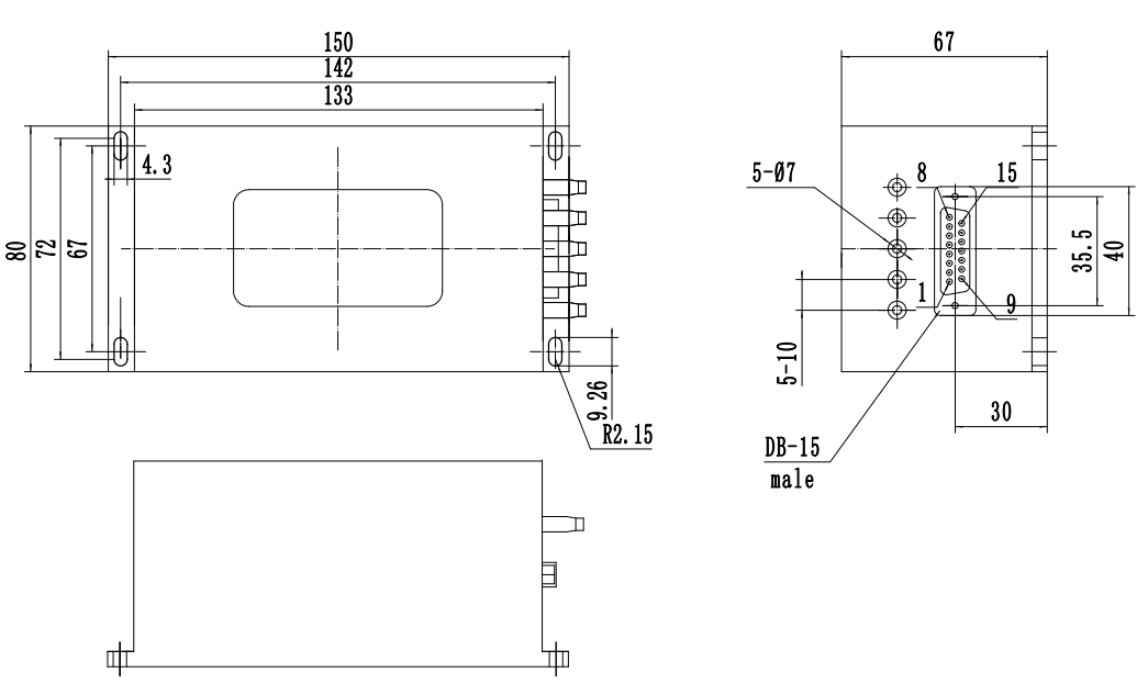
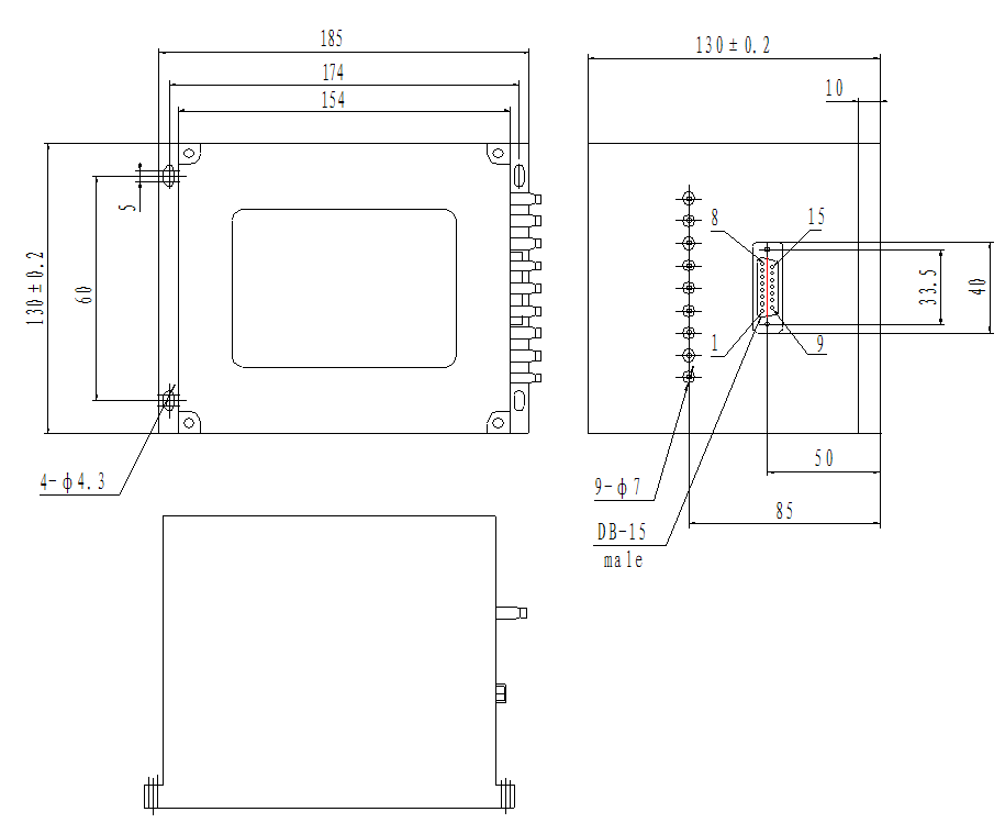
Dimension(DBx male head or female head is defined as the actual mark of the element)
Ø
Ø 02: 135×60×32-DB9 (N≤16, DB-9 male)
Ø 03: 135×60×32-DB15 (N≤18, DB-15 male)
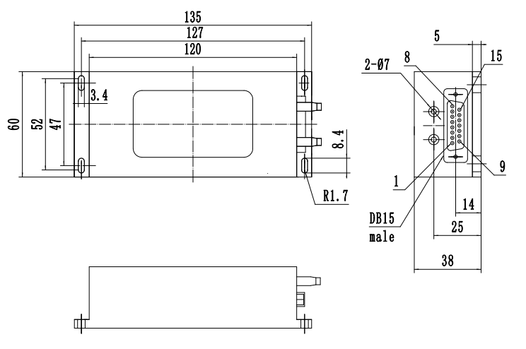
Ø 04: 135×60×38-DB15 (N≤32, DB-15 male)
Ø 05: 150×80×67-DB15 (N≤64, DB-15 male)
Ø 06: 185×130×130-DB15 (N≤128, DB-15 male)
Ordering Information: 7202-1×NL-T-A-B-C-D-E-F-G
Example:7202-1×8L-T-SM-FS-5-90-12-02M-FA
| A | B | C | D | E | F | G | H |
| Osw type | Fiber Type | Test Wavelength | Operating Voltage | Tube Type | Fiber Length | Dimension | Connector |
1×NL N=1~128 | SM: SM, 9/125 M5: MM, 50/125 M6: MM, 62.5/125 X: Others | 85: 850±40nm O: O band(1260~1360nm) C: C band(1530~1565nm) L: L band(1565~1625nm) U: U band(1625~1675nm) FS: 1260~1650nm | 5:5V | 25: 250um 90: 900um 20: 2mm 30: 3mm X: Others | 05: 0.5m±5m 10: 1.0m±5m 12: 1.2m±5m 15: 1.5m±5m X: Others | 01x: 135×40×32-DB9 02x: 135×60×32-DB9 03x: 135×60×32-DB15 04x: 135×60×38-DB15 05x: 150×80×67-DB15 06x: 135×130×130-DB15 X: Others x=F:female M:male | OO: None LP: LC/PC LU: LC/UPC LA: LC/APC FP: FC/PC FU: FC/UPC FA: FC/APC SP: SC/PC SU: SC/UPC SA: SC/APC STP: ST/PC STA: ST/APC X: Others |
Packing List
· 1pc optical fiber bypass switch
· 1pc user manual
· 1pc warranty card
Packing box of optical switch
FAQ:
Q1: Can i get a lower price? Any discount?
A1: Yes, we can offer discount for large quantity.
Q2: Can i get a free sample?
A2: Sorry, our sample is not for free.
Q3: How about the label and the logo?
A3: Customize label and logo is workable.
Q4: How about the MOQ?
A4: MOQ is 1PC
Q5: Warranty and after-sales issues.
A5: All our goods are 3 years warranty and our engineer will be online for any after-sales questions.


