
|
|
[China]

Trade Verify
Address: Building A2,Hutang Industrial zone,Lingdao Rd,Wujin District,Changzhou,China.Zip:213162
Contact name:Annie

CHANGZHOU JKONGMOTOR CO.,LTD |
|
Verified Suppliers
|
|
|
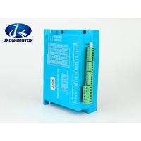
NEMA34 Closed Loop Stepper Motor Driver JK-HSD86 20V ~ 80VDC 0.1A -
10A
Electrical Specifications
| Parameter | Min | Typical | Max | Unit | |
| Input Voltage (JK-HSD86) | 20 | 36 48 | 50 | VDC | |
| Input Voltage (JK-HSD86C) | 24 | 36 48 | 80 | VDC | |
| Input Voltage (SC8680C) | 24VAC | 60AC | 80VAC 100VDC | VVDC | |
| Output Current | 0.1 | - | 10(Peak) | A | |
| Pulse Input Frequency | 0 | - | 200 | kHz | |
| Logic Signal Current | 7 | 10 | 16 | mA | |
| Isolation Resistance | 500 | - | - | MΩ | |
Operating Environment
| Cooling | Natural Cooling or Forced cooling | |
| Operating Environment | Environment | Avoid dust, oil fog and corrosive gases |
| Storage Temperature | -20℃ - 65℃ (-4℉ - 149℉) | |
| Ambient Temperature | 0℃ - 50℃ (32℉ - 122℉) | |
| Humidity | 40%RH - 90%RH | |
| Operating Temperature | 70℃ (158℉) Max | |
| (Heat Sink) | ||
| Weight | 580 g (20.5 oz) | |
Connectors and Pin Assignment
The JK-HSD86 has four connectors, connector for control signals
connections, connector for status signal connections,connector for
encoder feedback and connector for power and motor connections.
| Control Signal Connector | – | Screw Terminal | |||||||
| Pin | Name | I/O | Description | ||||||
| 1 | PUL+ | I | Pulse Signal: In single pulse (pulse/direction) mode, this input represents pulse signal, each | ||||||
| rising or falling edge active (software configurable, see easy servo drive software manual for | |||||||||
| more detail); In double pulse mode (software configurable), this input represents clockwise | |||||||||
| 2 | PUL- | I | |||||||
| (CW) pulse, active both at high level and low level. 4.5-28V when PUL-HIGH, 0-0.5V when | |||||||||
| PUL-LOW. For reliable response, pulse width should be longer than 2.0 | μ | s. | |||||||
| 3 | DIR+ | I | Direction Signal: In single-pulse mode, this signal has low/high voltage levels, representing | ||||||
| two directions of motor rotation. In double-pulse mode (software configurable), this signal | |||||||||
| is counter-clock (CCW) pulse, active both at high level and low level. For reliable motion | |||||||||
| response, DIR signal should be ahead of PUL signal by | 2us at least. 4.5-28V when DIR-HIGH, | ||||||||
| 4 | DIR- | I | |||||||
| 0-0.5V when DIR-LOW. Please note that rotation direction is also related to | |||||||||
| motor-driver-encoder wiring match. Exchanging both the connection of two wires for a coil | |||||||||
| and an encoder channel to the driver he connection will reverse motion direction. Or you | |||||||||
| can toggle the SW5 to reverse the motion direction. | |||||||||
| 5 | ENA+ | I | Enable Signal: This signal is used for enabling/disabling the driver. In default, high level | ||||||
| (NPN control signal) for enabling the driver and low level for disabling the driver. Usually | |||||||||
| left UNCONNECTED (ENABLED). Please note that PNP and Differential control signals are on | |||||||||
| 6 | ENA- | I | |||||||
| the contrary, namely Low level for enabling. The active level of ENA signal is software | |||||||||
| configurable. | |||||||||
Dimension:


