

Active Member
|
[China]

Address: 803, WeiXinDa, BaoMin 2nd Road, XiXiang, Bao'an District, Shenzhen, Guangdong Province, China.
Contact name:Orchard

Shenzhen Jelinn Technology Co., Ltd. |
|
|
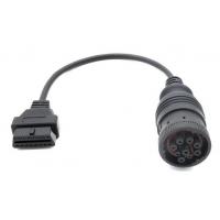
9-Pin Deutsch J1939 Female to J1962 OBD 16 Pin Female CAN Bus Cable
Specification
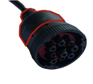
| J1939 female socket | equivalent of Deutsch HD16-9-1939S |
| Type of J1939 female socket | Type 1 |
| Color of J1939 female socket | Black |
| Wire | 20AWG, pure copper |
| Material of J1939 female socket | PA66 + glass fiber |
| Material of OBD2 female connector | PA66 |
| Pin assignment or pin out | customized |
| Cable length | customized |
| Pins or terminals | copper, nickel-plated or gold-plated |
| Contact Resistance | 3 ohm max. |
| Insulation Resistance | 5M ohm min. |
| Working Temperature | −25℃ ~ +85℃ |
| Testing | 100% open, short and miss-wire testing |
| Testing Voltage | DC300V 5M ohm/10ms |
| Warranty | 1 year |
The end of J1939 female socket can be overflow molded or not, according to your needs.
Overflow molded
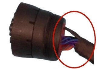
Not overflow molded
Pin assignment or pin out
Generally speaking, the pin assignment or pin out will be like this
(4 pins to be connected):
| OBD2 female | Signal | J1939 female |
| 4 or 5 | Ground | A |
| 16 | Battery | B |
| 6 | J1939, CAN-H | C |
| 14 | J1939, CAN-L | D |
Sometimes, the pin assignment or pin out can also be like this (6 pins to be connected):
| OBD2 female | Signal | J1939 female |
| 4 or 5 | Ground | A |
| 16 | Battery | B |
| 6 | J1939, CAN-H | C |
| 14 | J1939, CAN-L | D |
| 2 | J1708-H | F |
| 10 | J1708-L | G |
The 6-wire cable also includes wiring for the J1708 lines. If
you do not need the J1708 wires, it is better not to connect
them as sometimes the added lines can interfere with the
operation of some GPS trackers.
The pin assignment or pin out can also be customized according
to your needs.
Application
This is a cable between the J1939 round Deutsch 9-pin connector
(test equipment side - mates to the J1939 vehicle) and an OBD2
style 16-pin connector (female vehicle side - mates with an OBD2
test connector).
The most common application is to connect a GPS Tracker that is
meant for an OBD2 vehicle to a commercial vehicle that has the
9-pin round Deutsch connector. The power lines are appropriately
connected to provide power to the GPS tracker.
This cable will also allow an OBD2 diagnostic tool or scanner
or fault code reader (with the appropriate software) to connect to the round J1939
connector. Bear in mind that most OBD2 software and scanners are
based on reading PIDs, which are single parameters. J1939 is a PGN
based protocol, where each PGN contains multiple parameters. Your OBD2 diagnostic tool or scanner or fault code reader must be able to handle PGNs if it is to work with this cable.
Sending an inquiry
If you haven’t found or don’t have time to look for the J1939, OBD2
or J1708 cables, adapters or connectors in our website, feel
free to let us know what J1939, OBD2 or J1708 cables, adapters or
connectors you need by sending an inquiry (If you have a picture, please attach it in the inquiry). We can
also customize any J1939, OBD2 or J1708 cables, adapters or connectors for you.
Skype: orchard.guo (any time to contact)


