

Active Member
|
[China]

Address: #1,chencongxi10xiang,chencongcun,qiaonanjiedao,panyu,Guangzhou
Contact name:Lucy

Guangzhou Shice Equipment Co., Ltd. |
|
|
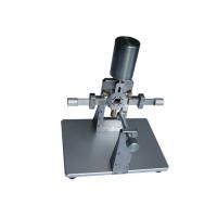
Apparatus Of Pin Movement Test AS / NZS 3112 Plug Socket gauge
| Standard | Product Name |
| AS/NZS3112 FigureA1 | Rating and Dimensions of low voltage plugs gauge Fig A1 (10A, 15A, 20A) |
| AS/NZS3112 Figure B1 | Rating and Dimensions of low voltage plugs gauge Fig B1 |
| AS/NZS3112 Figure C1 | During normal insertion test plug in Fig C1(10A,15A,20A) |
| AS/NZS3112 Figure D1 | During normal insertion test plug in Fig D1(10A,15A,21A) |
| AS/NZS3112 Figure E1 | Current breaking test /Test of temperature rise test plug with brass pins in Fig E1 |
| AS/NZS3112 Figure F1 a | Rating and Dimensions of low voltage plugs gauge Fig F1(a) Appendix F |
| AS/NZS3112 Figure F1 b | Rating and Dimensions of low voltage plugs gauge Fig F1(b) Appendix F |
| AS/NZS3112 Figure G1 a | During normal insertion test plug in Fig G1(a) of Appendix G |
| AS/NZS3112 Figure G1 b | During normal insertion test plug in Fig G1(b) of Appendix G |
| AS/NZS 3112 figure 3.1 abc | Depth of contact No-contact gauge in Fig 3.1 a b c |
| AS/NZS 3112 figure 3.1 abc clause 3.3.4 | Depth of contact Contact gauge in Fig 3.1 a b c |
| AS/NZS 3112 figure 3.1 a | Contact gauge in Fig 3.1 a (metal blade 1.58x6.2mm,length 12.60mm) |
| AS/NZS 3112 figure 3.1 b | Contact gauge in Fig 3.1 b (metal blade 1.58x8.93mm,length 12.60mm) |
| AS/NZS 3112 figure 3.1 c | Contact gauge in Fig 3.1 c (metal pin: Ф4.7mm,length 12.60mm) |
| AS/NZS 3112 figure 3.6 | Test of lateral strain gauge Fig 3.6 |
| AS/NZS 3112 figure 3.7 | Test of lateral strain gauge Fig 3.7 |
| AS/NZS 3112 figure 2.1 a1 | Test plug with brass pins in Figure 2.1(a1)10A |
| AS/NZS 3112 figure 2.1 a1 | Test plug with brass pins in Figure 2.1(a1)15A |
| AS/NZS 3112 figure 2.1 a2 | Test plug with brass pins in Figure 2.1(a2) |
| AS/NZS 3112 figure 2.1 b | Test plug with brass pins in Figure 2.1(b) |
| AS/NZS 3112 figure 2.1 c | Test plug with brass pins in Figure 2.1(c) |
| AS/NZS 3112 figure 2.1 d1 | Test plug with brass pins in Figure 2.1(d1) |
| AS/NZS 3112 figure 2.1 d2 | Test plug with brass pins in Figure 2.1(d2) |
| AS/NZS 3112 figure 2.1 f | Test plug with brass pins in Figure 2.1(f) |
| AS/NZS 3112 figure 2.1 g | Test plug with brass pins in Figure 2.1(g) |
| AS/NZS 3112 Clause 3.3.2 | Test pin gauge 1.5N 6.20mm x 1.58mm |
| AS/NZS 3112 Clause 3.3.2 | Test pin gauge 2N 6.20mm x 1.58mm |
| AS/NZS 3112 Clause 3.3.2 | Test pin gauge 3N 6.20mm x 1.58mm |
| AS/NZS 3112 Figure 2.1 | Test Jig |
| AS/NZS 3112 Clause 2.13.8 | Wooden mounting box in Figure 2.9 |
| AS/NZS 3112 Clause 2.13.8 | Pin clamping unit in Figure 2.10 a, b, c |
| AS/NZS 3112 Clause 3.6.3 | modified gauge of Appendix D (diameter changed to 43.2mm) |
| AS/NZS 3112 Clause 3.14.2 | metallic enclosure H90mm x W60mm xD40mm with fixing hole |
| AS/NZS 3112 Clause 2.2.3 | Form of pin in Figure 2.3 |
Application
Plugs shall be tested for pin movement by clamping the pin or pins not under test in a rigid
holding block positioned 5±0.5 mm from the plug face and applying force of 18±1N to
the pin under test. The design of the block shall be such that the pin under test shall not
come into contact with the block during the test
Except for non-rewireable plugs, the test shall be carried out without a cord attached to the
plug, and with the terminal screws loosened sufficiently to allow 1 mm2 conductor to be
connected.
The plug and test equipment shall be preconditioned at temperature of 40±1 degree for 1h
without the test force applied. Throughout the test, all parts of the plug and test equipment
shall be maintained at this temperature.
For all plugs, the point of application of the force shall be 140.5 mm from the face of the
plug along the pins, and the direction of the force shall be
(a) in both directions along the line perpendicular to the plane of the pin, and passing
through the centre of the pin; and
(b)in that plane in both directions along a line at right angles to that specified in
Item (a)
Over a period of 10 s, the force shall be gradually applied to each of the pins in the manner
prescribed in Items (a)and (b), maintained at its maximum value for 10 s, and then
released. The deflection of the pins shall be measured along the line of force relative to the
face of the rigid holding block during the period when the force is applied. The maximum
deflection shall not exceed 2.0 mm.
Following the test on all pins of a plug conforming to Figure 2.1, any distortion 5 min after
the completion of the test on the last pin shall be such that it will not prevent the plug from
being inserted in the appropriate standard gauges shown in Appendix A, Appendix and
Appendix F without the application of undue forcc
For other types of plugs, any distortion after 5 min shall be such that will not prevent the
plug being inserted into an appropriate socket-outlet without the application of undue force.
ConformsTo
AS/NZS 3112:2011 +A2:2012 clause 2.13.9.1
Specifications
Force:18±1N
Ordering Information
Test apparatus for pin movement test AS/NZS 3112


