
|
|
[China]

Trade Verify
Address: 23E BlockB,Lushan Building,Chunfeng Road,Luohu District,Shenzhen,518001,China
Contact name:Eva

Shenzhen Wisdomlong Technology CO.,LTD |
|
Verified Suppliers
|
|
|
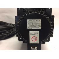
Yaskawa NEW ORIGINALS 450W 1500r/min ELECTRIC SERVO MOTOR SGMGH-05DCA61
Specifications
OTHER SUPERIOR PRODUCTS
| Yasakawa Motor, Driver SG- | Mitsubishi Motor HC-,HA- |
| Westinghouse Modules 1C-,5X- | Emerson VE-,KJ- |
| Honeywell TC-,TK- | GE Modules IC - |
| Fanuc motor A0- | Yokogawa transmitter EJA- |
| SGMGH-03ACB61 |
| SGMGH-03ACB6C |
| SGMGH-05A2A2B |
| SGMGH-05A2A61 |
| SGMGH-05A2ASC61 |
| SGMGH-05ACA61 +SGDM-05ADA |
| SGMGH-05ACA6C |
| SGMGH-05ACC21 |
| SGMGH-09A2A21 |
| SGMGH-09ACA21 |
| SGMGH-09ACA2B |
| SGMGH-09ACA2C |
| SGMGH-09ACA61 |
| SGMGH-09ACA6B |
| SGMGH-09ACA6C |
| SGMGH-09ACB61 |
| SGMGH-09ACB6B |
| SGMGH-09PCA-AM14 |
| SGMGH-12A2B2 |
| SGMGH-12A2B21 |
| SGMGH-13A2A-YR13 |
| SGMGH-13A2A-YR23 |
| SGMGH-13A2A-YR23A |
| SGMGH-13A2A-YR24 |
| SGMGH-13ACA |
| SGMGH-13ACA21 |
| SGMGH-13ACA61 |
| SGMGH-13ACA6C |
| SGMGH-13DCA61 |
| SGMGH-1AACA61 |
| SGMGH-1EACA61 |
| SGMGH-20A2B2C |
| SGMGH-20ABA6C |
| SGMGH-20ACA61 |
| SGMGH-20ACA6B |
| SGMGH-20ACA6C |
| SGMGH-20ACB2C |
| SGMGH-20ACB61 |
| SGMGH-20D2A21 |
Grounding
(a) Motor Frame
Always connect servomotor frame terminal FG to the SERVOPACK ground terminal . Also be sure to ground the ground terminal .
If the servomotor is grounded via the machine, a switching noise current will flow from the SERVOPACK power unit through motor stray capacitance. The above grounding is required to prevent the adverse effects of switching noise.
(b) SynqNet Communication Cable
Make sure to keep the box or power line separate from the SynqNet communication cable because the cable is easily influenced by noise.
If noise is a problem, coil the communication cable two turns around the ferrite cores on the SERVOPACK end and the controller end. Refer to the following diagram.
(c) Noise on the Reference Input Line
If the reference input line receives noise, ground the 0 V line (SG) of the reference input line. If the main circuit wiring for the motor is accommodated in a metal conduit, ground the conduit and its junction box. For all grounding, ground at one point only.
All grounds must be made to only one point in the system.


