
|
|
[China]

Trade Verify
Address: 23E BlockB,Lushan Building,Chunfeng Road,Luohu District,Shenzhen,518001,China
Contact name:Eva

Shenzhen Wisdomlong Technology CO.,LTD |
|
Verified Suppliers
|
|
|
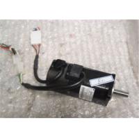
Yaskawa servo motor 100W 0.91A Industrial Servo Motor 200V SGMAH-01A1A-SM11
Specifications
Servomotor Type: SGMAH Sigma II
Rated Output: 200W (0.25HP)
Power Supply: 200V
Encoder Specifications: 16-bit (16384 x 4) Absolute Encoder; Standard
Revision Level: Standard
Shaft Specifications: Straight shaft without keyway
Accessories: Standard; without brake
Option: None
Function:Power Triode
Construction:Point Contact TypeStructure:PNP
Special Function:Common Point Contact
DiodeUsage:Light-emitting Diode
Type: none
OTHER SUPERIOR PRODUCTS
| Yasakawa Motor, Driver SG- | Mitsubishi Motor HC-,HA- |
| Westinghouse Modules 1C-,5X- | Emerson VE-,KJ- |
| Honeywell TC-,TK- | GE Modules IC - |
| Fanuc motor A0- | Yokogawa transmitter EJA- |


