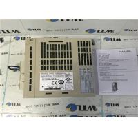
Industrial Servo Drives YASKAWA ELECTRIC SGDM-02ADAY402 0.20Kw
Inout 3.4A
Quick Details
Brand Name:Yaskawa
Model Number: SGDM-02ADAY402
Input Voltage:200-230V
Input currentt:3.4A
Input Frequency:50/60HZ
Input PH : 1
Output Power : 0.20KW
Output Voltage: 0-230V
Output Current: 2.1A
Output Frequency:0-300Hz
Output PH :3
Temperture: 0-55℃
Place of Origin:Japan
Efficiency:IE 1
OTHER SUPERIOR PRODUCTS
| Yasakawa Motor, Driver SG- | Mitsubishi Motor HC-,HA- |
| Westinghouse Modules 1C-,5X- | Emerson VE-,KJ- |
| Honeywell TC-,TK- | GE Modules IC - |
| Fanuc motor A0- | Yokogawa transmitter EJA- |
Contact person: Anna
E-mail: wisdomlongkeji@163.com
Cellphone: +0086-13534205279
Similar Products
| SGDM-10ADA |
| SGDM-10ADG-P |
| SGDM-10AN-P |
| SGDM-15AC-SD1 |
| SGDM-15ADA |
| SGDM-15ADA.SGDH-15AE |
| SGDM-1AADA |
| SGDM-1EADA |
| SGDM-20AC-SD1 |
| SGDM-20AC-SD2B |
| SGDM-20AC-SD2BM |
| SGDM-20ADA |
| SGDM-20ADA-V |
| SGDM-20ADA-Y47 |
| SGDM-30AC-SD1 |
| SGDM-30ADA |
| SGDM-30ADA-V |
| SGDM-50AC-SD1 |
| SGDM-50ADA |
| SGDM-50ADAY60 |
| SGDM-60AC-SD1 |
| SGDM-60ADA |
| SGDM-75AC-SD1 |
| SGDM-75ADA |
| SGDM-A3ADA |
| SGDM-A3ADA+SGMAH-A3AAAJ36C |
| SGDM-A3ADA+SGMAH-A3ABA21 J |
| SGDM-A3ADA-R |
| SGDM-A3BD |
| SGDM-A3BDA |
| SGDM-A3BDAY278 |
| SGDM-A5ADA |
| SGDM-A5ADA+SGMAH-A5AAA21 |
| SGDM-A5ADA-R |
| SGDM-A5ADA-TE3B |
| SGDM-A5AD-RY90+SGMAH-A5AAA21 |
| SGDM-A5ADY90 |
For each octave band, a set of test frequencies was defined. Each
equal sensation test consisted of
exposing a subject to the reference then to one of the test
frequencies chosen randomly from the set for
the octave band in question. When all test frequencies for the band
were completed, the highest
frequency was set as the new reference signal for the next octave
band under investigation and the
amplitude given by the test subject during their test of that
frequency was taken as the new reference
amplitude. By means of this procedure, and starting from the lowest
reference frequency of the particular
equal sensation curve (either 10 or 40 Hz), the tests were
propagated to higher frequencies until all 1/3
octave band frequencies were tested from 5 to 315 Hz. Setting new
reference signals after every doubling
of frequency produced reference signals at 10, 20, 40 ,80 160 and
315 Hz. By means of this procedure
every frequency from 10 Hz to 160 Hz was tested twice, once with
reference to a lower frequency and
once with reference to a higher frequency. The average of the two
results was taken for all calculations.
For the annoyance threshold tests, an approach known as “Up and
Down” Method of Limits (i.e Von
Bekesy Method) was used [4,9]. In this approach the experimenter
made adjustments which depended
on the response of the subject. The adjustments involved three
steps. The magnitude of vibration was
first increased in small increments until the subjects perceived it
as “annoying”. The subjects were asked
to indicate the vibration level which produced an annoyance that
they could withstand for 10 seconds.
Then the magnitude was decreased until they perceive it as “not
annoying”. To increase the accuracy and
avoid overshooting the magnitude by the experimenter, the vibration
level was increased again until the
subjects perceive it as “annoying”. All center frequencies of 1/3
octave band from 5 Hz to 315 Hz were
used as the test signals. Signals were presented in a random order
to avoid learning effects.
Test Protocol
Each equal sensation test lasted approximately 30 minutes and each
annoyance test lasted about 20
minutes. Each test consisted of 7 main phases as outlined in Table
4. Prior to testing, a consent form was
given and information was gathered from each subject regarding
their anthropometry, health, driving
experience and previous vibration exposure. A trial run was
conducted to familiarize the subjects with the
method before acquiring any data. Not more than two tests were
allowed for each subject in a day to
avoid fatigue and learning effects. During all tests, subjects were
asked to wear ear protectors and blind
glasses to avoid visual and audio interferences.