

Active Member
|
[China]

Address: 3418, Duhuixuan, Shennan Avenue, Futian District, Shenzhen, Guangdong Province, China
Contact name:段

Shenzhen Hongxinwei Technology Co., Ltd |
|
|
TLV237x 500-µA/Ch, 3-MHz Rail-to-Rail Input and Output Operational Amplifiers With Shutdow
1 1 Features 1• Rail-to-Rail Input and Output • Wide Bandwidth: 3 MHz • High Slew Rate: 2.4 V/μs • Supply Voltage Range: 2.7 V to 16 V • Supply Current: 550 μA/Channel • Low-Power Shutdown Mode – IDD(SHDN): 25 μA/Channel • Input Noise Voltage: 39 nV/√Hz • Input Bias Current: 1 pA • Specified Temperature Range: – −40°C to +125°C (Industrial Grade) • Ultra-Small Packaging: – 5- or 6-Pin SOT-23 (TLV2370, TLV2371) – 8- or 10-Pin MSOP (TLV2372, TLV2373) 2 Applications • White Goods • Handheld Test Equipment • Portable Blood Glucose Systems • Remote Sensing • Active Filters • Industrial Automation • Battery-Powered Electronics Operational Amplifier 3 Description The TLV237x single-supply operational amplifiers provide rail-to-rail input and output capability. The TLV237x takes the minimum operating supply voltage down to 2.7 V over the extended industrial temperature range while adding the rail-to-rail output swing feature. The TLV237x also provides 3-MHz bandwidth from only 550 μA. The maximum recommended supply voltage is 16 V, which allows the devices to be operated from (±8-V supplies down to ±1.35 V) a variety of rechargeable cells. The CMOS inputs enable use in high-impedance sensor interfaces, with the lower voltage operation making an ideal alternative for the TLC227x in battery-powered applications. The rail-to-rail input stage further increases its versatility. The TLV237x is the seventh member of a rapidly growing number of RRIO products available from TI, and it is the first to allow operation up to 16-V rails with good ac performance. All members are available in PDIP and SOIC with the singles in the small SOT-23 package, duals in the MSOP, and quads in the TSSOP package. The 2.7-V operation makes the TLV237x compatible with Li-Ion powered systems and the operating supply voltage range of many micro-power microcontrollers available today including TI’s MSP430. Device Information(1) PART NUMBER PACKAGE BODY SIZE (NOM) TLV237x PDIP (8) 9.81 mm × 6.35 mm PDIP (14) 19.30 mm × 6.35 mm SOIC (8) 4.90 mm × 3.91 mm SOIC (14) 8.65 mm × 3.91 mm TSSOP (14) 5.00 mm × 4.40 mm TSSOP (16) SOT-23 (6) 2.90 mm × 1.60 mm SOT-23 (5) VSSOP (8) 3.00 mm × 3.00 mm VSSOP (10) (1) For all available packages, see the orderable addendum at the end of the data sheet.
To achieve the levels of high performance of the TLV237x, follow
proper printed-circuit board design techniques. A general set of
guidelines is given in the following. • Ground planes—TI highly
recommends using a ground plane on the board to provide all
components with a low inductive ground connection. However, in the
areas of the amplifier inputs and output, the ground plane can be
removed to minimize the stray capacitance. • Proper power supply
decoupling—Use a 6.8-μF tantalum capacitor in parallel with a
0.1-μF ceramic capacitor on each supply terminal. It may be
possible to share the tantalum among several amplifiers depending
on the application, but a 0.1-μF ceramic capacitor should always be
used on the supply terminal of every amplifier. In addition, the
0.1-μF capacitor must be placed as close as possible to the supply
terminal. As this distance increases, the inductance in the
connecting trace makes the capacitor less effective. The designer
should strive for distances of less than 0.1 inches between the
device power terminals and the ceramic capacitors. •
Sockets—Sockets can be used but are not recommended. The additional
lead inductance in the socket pins will often lead to stability
problems. Surface-mount packages soldered directly to the
printed-circuit board is the best implementation. • Short trace
runs and compact part placements—Optimum high performance is
achieved when stray series inductance has been minimized. To
realize this, the circuit layout must be made as compact as
possible, thereby minimizing the length of all trace runs. Pay
particular attention to the inverting input of the amplifier. Its
length must be kept as short as possible. This helps to minimize
stray capacitance at the input of the amplifier. • Surface-mount
passive components—Using surface-mount passive components is
recommended for high performance amplifier circuits for several
reasons. First, because of the extremely low lead inductance of
surface-mount components, the problem with stray series inductance
is greatly reduced. Second, the small size of surface-mount
components naturally leads to a more compact layout thereby
minimizing both stray inductance and capacitance. If leaded
components are used, TI recommends that the lead lengths be kept as
short as possible. 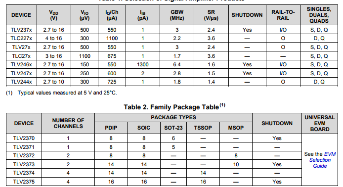
Q1. What is your terms of packing?
A: Generally, we pack our goods in neutral white boxes and brown cartons.
If you have legally registered patent, we can pack the goods in your branded boxes after getting your authorization letters.
Q2. What is your MOQ?
A: We provide you small MOQ for each item, it depends your specific order!
Q3. Do you test or check all your goods before delivery?
A: Yes, we have 100% test and check all goods before delivery.
Q4: How do you make our business long-term and good relationship?
We keep good quality and competitive price to ensure our customers benefit ;
We respect every customer as our friend and we sincerely do business and make friends with them,It's not something that can be replaced.
Q5: How to contact us?
A: Send your inquiry details in the below,Click "Send"Now!!!
Shenzhen Hongxinwei Technology Co., Ltd
To adopt new technology,to produce products of quality,to offer high-class service.
Improve the management system continuously to meet customer requirement for high-quality products and services.
Why choose us?


