|
|
[China]

Trade Verify
Contact name:Sherlin

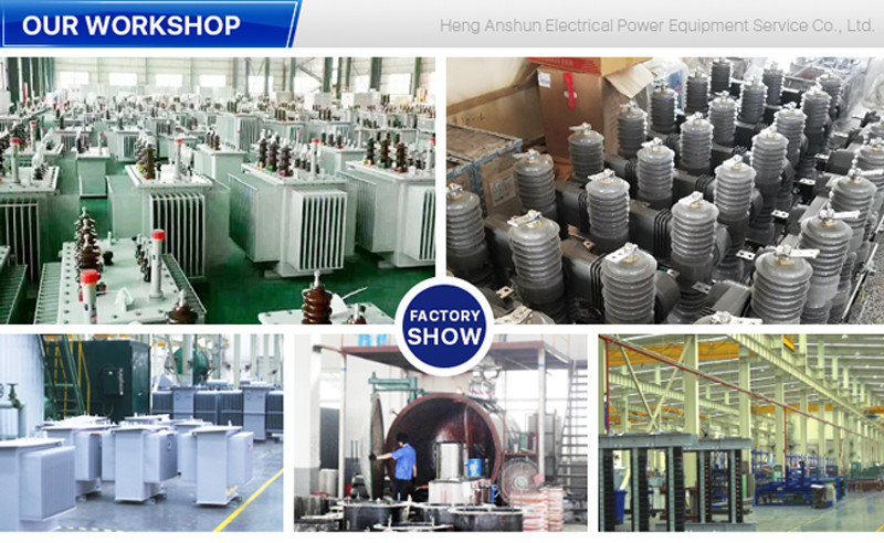
GuangDong Heng AnShun Electrical Power Equipment Service Co., Ltd. |
|
Verified Suppliers
|
|
|
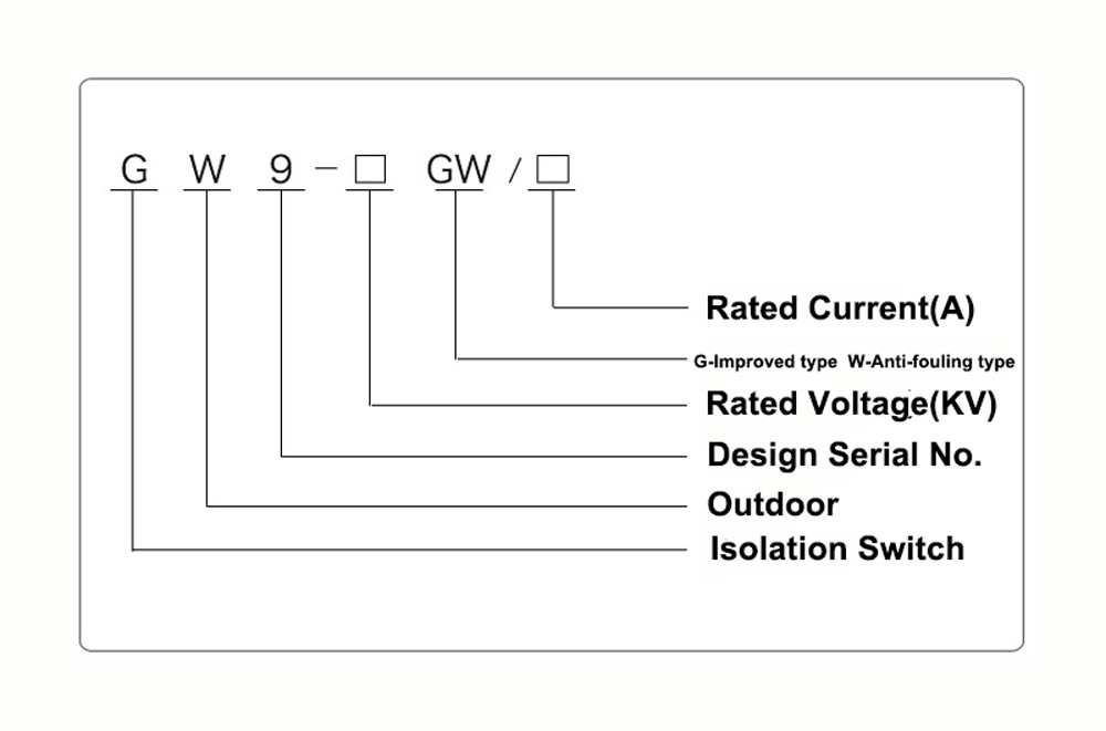
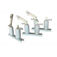
Single Phase High Voltage Electrical Isolator With Safety Operation And Easy Installation Vertical Break Switch
Product Decription:
The high-voltage electrical isolator, also known as a disconnect
switch, is specifically designed to disconnect or isolate a section
of an electrical circuit from its power source. It provides a
physical break in the circuit, allowing maintenance personnel to
work on the equipment safely without the risk of electric shock.
The disconnect isolator does not provide any arc-quenching
capabilities like a circuit breaker.
In high-voltage power systems, the high-voltage isolator switchr
and the vacuum circuit breake are often coordinated to work
together. The circuit breaker is responsible for detecting faults
and tripping to interrupt the current flow, while the disconnect
isolator is used to physically isolate the circuit and provide a
visible indication of the disconnection.
The high-voltage electrical isolator plays a crucial role in
ensuring the safety of maintenance personnel. Before any
maintenance work can be performed on the electrical equipment, the
disconnect isolator is operated to open the circuit and provide a
visible air gap. This ensures that the equipment is de-energized
and safe to work on.
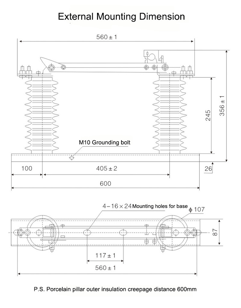
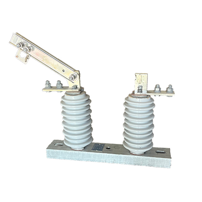
Structure:
1.Porcelain Insulator Body: The insulator body is the main component of the isolator, and is typically made of high-strength porcelain. It is designed to provide electrical insulation between the conductor and supporting structure, and is molded into the desired shape and size.
2.Metal End Fittings: The metal end fittings are attached to the insulator body and provide a means of connecting the isolator to the conductor and supporting structure. They are typically made of galvanized steel or other corrosion-resistant material, and may be designed with special features such as clevises or ball-and-socket joints for easy installation.
3.Sealing Compound: A sealing compound is used to seal the joint between the insulator body and metal end fittings, preventing moisture and contaminants from entering the interior of the isolator.
4.Hardware: Hardware such as bolts, nuts, and washers are used to secure the metal end fittings to the insulator body and supporting structure.
Fitting Caps: Fitting caps are used to protect the metal end fittings from corrosion and damage, and may be made of plastic or other materials.
5.Additional Features: Depending on the specific application, porcelain high voltage electrical isolators may be designed with additional features such as insulating barriers, arc chutes, and earth switches to improve their performance and safety.
Operation:
1.Interoperability: High voltage disconnect switches are designed
to integrate with other components of the electrical system, such
as circuit breakers, transformers, or protective relays. This
interoperability allows for coordinated operation and protection of
the entire system, ensuring reliable and efficient power
distribution.
2.Remote monitoring and diagnostics: Some high voltage disconnect
switches are equipped with remote monitoring and diagnostics
capabilities. These systems enable real-time monitoring of switch
parameters, such as temperature, pressure, and contact resistance,
allowing for proactive maintenance and troubleshooting to prevent
failures and optimize performance.
3.Emergency operation: High voltage disconnect switches may have
provisions for emergency operation, such as manual overrides or
emergency power supplies. These features ensure that the switch can
be operated even in emergency situations, such as power outages or
equipment failures, providing an additional layer of reliability
and safety.
4.Compliance with standards: High voltage disconnect switches are
designed and manufactured to meet industry standards and
regulations, ensuring their safety and performance. Compliance with
standards such as IEC, ANSI, or NEMA guarantees that the switch has
undergone rigorous testing and meets the necessary requirements for
operation in high voltage applications.
Application:
1.Circuit Isolation: High voltage isolator switches are used to isolate a section of a high voltage circuit for maintenance, repair, or testing purposes. By opening the switch, the section can be effectively disconnected from the rest of the system, allowing work to be carried out safely.
2.Load Switching: High voltage isolator switches can be used as load switches to control the flow of electrical power in a circuit. They are particularly useful in situations where the load is relatively small and does not require a circuit breaker or fuse.
3.Overhead Line Protection: High voltage isolator switches are often installed on overhead power lines to provide protection against lightning strikes and other electrical disturbances. By isolating a section of the line, the switch can help prevent damage to equipment and reduce the risk of power outages.
4.Transformer Protection: High voltage isolator switches are also used to protect transformers by isolating them from the electrical network in the event of a fault or overload. By opening the switch, the transformer can be disconnected from the network, preventing damage to the transformer and other equipment.
Condition:
1.The maximum altitude for installation should not exceed 1000m.
2.The ambient air temperature should not exceed +40'C, and in general areas, it should not fall below -30'C. In Paramos areas, it should not fall below -40'C.
3.The wind pressure should not exceed 700Pa, corresponding to a wind speed of 34m/s.
4.The isolator should be able to withstand earthquakes of up to 8 degrees in intensity.
5.The isolator should be installed in a location where there is no frequent violent vibration.
6.For ordinary type isolators, they should be kept away from gas, smoke, chemical deposition, salt-spray fog, dust, and other explosive and corrosive materials that can seriously affect the isolator's insulation and conduction capability.
7.Pollution-proof type isolators are suitable for use in severely filthy conduction areas, but they should not be installed in areas with any explosive or fire-causing materials.
Technical Parameters:
| Serial No. | Parameter | Unit | Data | |||||||||
| 1 | Rated Voltage | kV | 12 | |||||||||
| 2 | Rated Current | Model No. | (H)GW9-12(W)/630-20 | A | 630 | |||||||
| (H)GW9-12(W)/1000-20 | 1000 | |||||||||||
| (H)GW9-12(W)/1250-31.5 | 1250 | |||||||||||
| 3 | 4s Short-time withstanding current | Model No. | (H)GW9-12(W)/630-20 | kA | 50 | |||||||
| (H)GW9-12(W)/1000-20 | 50 | |||||||||||
| (H)GW9-12(W)/1250-31.5 | 80 | |||||||||||
| 4 | Rated Insulation Level | Lightning surge withstand voltage(peak) | Polar-to-Earth (Positive & Negative) | kV | 75 | |||||||
| Interfracture (Positive & Negative) | 85 | |||||||||||
| Industrial frequency withstand voltage (1 min) (Effective value) | Dry Test/Wet Test | Polar-to-Earth | 42(Dry) 34(Wet) | |||||||||
| Interfracture | 48(Dry) | |||||||||||
| 48(Dry) | ||||||||||||
| 48(Dry) 40(Wet) | ||||||||||||
| 5 | Main Circuit Resistance | μ Ω | 630 | |||||||||
| 1000 | ||||||||||||
| 1250 | ||||||||||||
| 6 | Mechanical Life Time | times | 50 | |||||||||
| 50 | ||||||||||||
| 80 | ||||||||||||