|
|
[China]

Trade Verify
Contact name:Sherlin

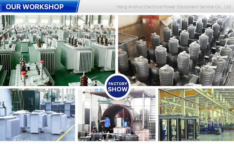
GuangDong Heng AnShun Electrical Power Equipment Service Co., Ltd. |
|
Verified Suppliers
|

|
|
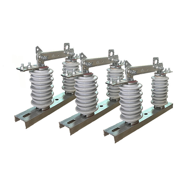
Outdoor Hookstick Switch 1 Pole Automatic Controlled Electrical Isolator Installed For Overhead Power Lines
Product Decription:
High Voltage elctrical isolator is an electrical switch used
for isolating a single-phase high voltage circuit from its power
source. It is typically used in power distribution systems to
provide a safe means of disconnecting power to a specific section
of the circuit for maintenance or repair purposes.The switch
typically consists of a set of contacts that can be opened or
closed manually or automatically, depending on the application.
When the switch is in the closed position, current can flow through
the circuit, and when the switch is open, the circuit is
disconnected from the power source.
The isolator switch is typically equipped with a set of
contacts that can be operated manually or automatically, depending
on the specific application and system requirements. By opening or
closing these contacts, the switch controls the flow of current in
the circuit. When the switch is closed, the circuit is connected to
the power source, allowing current to flow. Conversely, when the
switch is open, the circuit is disconnected from the power source,
effectively interrupting the current flow.
Advantage:
1.Simple structure: The isolation switch is designed with a straightforward structure, making it easy to understand and operate.
Low maintenance: Due to its design and construction, the isolation switch requires minimal maintenance, reducing the need for frequent inspections and repairs.
2.High breaking and closing linearity: The isolation switch has excellent breaking and closing linearity, ensuring smooth and reliable operation during switching operations.
3.High reliability: The switch is built to provide dependable performance, minimizing the risk of malfunctions or failures during operation.
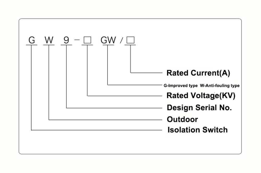
4.Comparable to international standards: The GW9-12(W) series isolation switch meets or exceeds the level of similar products both domestically and internationally, ensuring its compatibility and competitiveness in the market.
Structure:
1.Porcelain Insulator Body: The insulator body is the main component of the isolator, and is typically made of high-strength porcelain. It is designed to provide electrical insulation between the conductor and supporting structure, and is molded into the desired shape and size.
2.Metal End Fittings: The metal end fittings are attached to the insulator body and provide a means of connecting the isolator to the conductor and supporting structure. They are typically made of galvanized steel or other corrosion-resistant material, and may be designed with special features such as clevises or ball-and-socket joints for easy installation.
3.Sealing Compound: A sealing compound is used to seal the joint between the insulator body and metal end fittings, preventing moisture and contaminants from entering the interior of the isolator.
4.Hardware: Hardware such as bolts, nuts, and washers are used to secure the metal end fittings to the insulator body and supporting structure.
Fitting Caps: Fitting caps are used to protect the metal end fittings from corrosion and damage, and may be made of plastic or other materials.
5.Additional Features: Depending on the specific application, porcelain high voltage electrical isolators may be designed with additional features such as insulating barriers, arc chutes, and earth switches to improve their performance and safety.
Safety Tips:
1.Conduct routine testing and maintenance on the switch to ensure its proper functioning. This includes testing the switch's insulation resistance, verifying the operation of safety interlocks, and checking for any abnormal heating or vibrations.
2.Implement a lockout/tagout procedure before performing maintenance or repair work on the switch. This procedure involves locking and tagging the switch to prevent accidental energization while work is being carried out, providing an additional layer of safety.
3.Provide adequate training to personnel who will be operating or working on the switch. Training should cover proper handling, operation, and maintenance procedures, as well as the potential hazards associated with the switch.
4.Implement a comprehensive safety management system that includes regular safety audits, hazard assessments, and incident reporting. This proactive approach to safety helps identify and address potential risks before they result in accidents or injuries.
5.Ensure proper ventilation and cooling systems are in place for high voltage isolator switches located in enclosed or confined spaces. 6.Adequate ventilation helps dissipate heat and prevents the switch from overheating, which can lead to malfunctions or even fires.
Condition:
1.The altitude does not exceed 1000m
2.The ambient air temperature: Maximum+ 40'C ;Minimum:General Area -30'C, Paramos -40 C;
3.The wind pressure does not exceed 700Pa.(corresponding to 34m/s wind speed);
4.The earthquake intensity does not exceed 8 degrees;
5.The working situation is without frequent violent vibration;
6.The installation site of ordinary type isolator should be kept away form gas, smoke chemical deposition, salt-spray fog, dust
and other explosive and corrosive maters that affect seriously insulation and conduction capability of the isolator
7.Pollution-proof type isolator is applies to severe filthy conduction area, however, it shouldn't be any explosive matters and matters causing fire
Technical Parameters:
| Serial No. | Parameter | Unit | Data | |||||||||
| 1 | Rated Voltage | kV | 12 | |||||||||
| 2 | Rated Current | Model No. | (H)GW9-12(W)/630-20 | A | 630 | |||||||
| (H)GW9-12(W)/1000-20 | 1000 | |||||||||||
| (H)GW9-12(W)/1250-31.5 | 1250 | |||||||||||
| 3 | 4s Short-time withstanding current | Model No. | (H)GW9-12(W)/630-20 | kA | 50 | |||||||
| (H)GW9-12(W)/1000-20 | 50 | |||||||||||
| (H)GW9-12(W)/1250-31.5 | 80 | |||||||||||
| 4 | Rated Insulation Level | Lightning surge withstand voltage(peak) | Polar-to-Earth (Positive & Negative) | kV | 75 | |||||||
| Interfracture (Positive & Negative) | 85 | |||||||||||
| Industrial frequency withstand voltage (1 min) (Effective value) | Dry Test/Wet Test | Polar-to-Earth | 42(Dry) 34(Wet) | |||||||||
| Interfracture | 48(Dry) | |||||||||||
| 48(Dry) | ||||||||||||
| 48(Dry) 40(Wet) | ||||||||||||
| 5 | Main Circuit Resistance | μ Ω | 630 | |||||||||
| 1000 | ||||||||||||
| 1250 | ||||||||||||
| 6 | Mechanical Life Time | times | 50 | |||||||||
| 50 | ||||||||||||
| 80 | ||||||||||||