|
|
[China]

Trade Verify
Contact name:Sherlin

GuangDong Heng AnShun Electrical Power Equipment Service Co., Ltd. |
|
Verified Suppliers
|
|
|
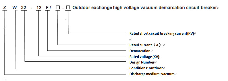
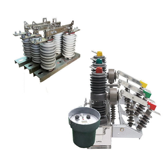
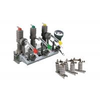
Intelligent Demarcation Electrical Sectionlizer With Controller Matching With Hookstick Switch Supports Communication
Product Description:
ZW32 Series intelligent demarcation electrical sectionlizer is an outdoor distribution equipment with rated voltage of 12kV and three-phase alternating current of 50Hz.It is mainly used to open and close load current, overload current and short circuit current in power system.It is suitable for the protection and control in the power distribution system of substation and industrial and mining enterprises, as well as the places where the rural power grid is frequently operated. The circuit breaker has the characteristics of small volume, light weight, anti-condensation, free maintenance and so on. It can adapt to the harsh weather conditions and dirty environment.
GW9-10 hookstick switch is a type of electrical switch used to isolate a section of an overhead power transmission line for maintenance or repair. It is typically used in high voltage electrical systems, such as those used by power utilities to transmit electricity over long distances.
The switch is mounted on an overhead structure, such as a transmission tower or pole, and is designed to withstand the harsh environmental conditions encountered in outdoor electrical systems. It features a vertical, or up-and-down, motion to engage or disengage the switch contacts, which are typically made of copper or other conductive materials.
The hookstick switch is designed to provide a visible break in the transmission line, allowing maintenance personnel to safely work on the line without risk of electrocution or damage to equipment. It is often used in conjunction with other safety devices, such as grounding switches and surge arrestors, to protect the electrical system and the people working on it.
Double effect of using when GW9-10 series isolator swich can be used with the vacuum circuit breakers.
Controller Introduction:
The controller supports communication via a 485/232 interface,
which allows for remote monitoring and control. It can also
communicate through optical fiber or wireless connections.
When a heavy switch is detected, the device automatically
accelerates the tripping process in the event of a permanent fault.
This feature helps protect the system from damage in such
situations.
Remote/Manual Closing and Reclosing: The user has the option to
remotely or manually close and reclose the circuit. Additionally,
if the user forgets to remove the grounding switch when restoring
power after repairing a line, the device can accelerate the
tripping process to ensure safety.
It allows for the adjustment of three reclosing delay times. This
feature provides flexibility in determining the appropriate delay
before reclosing the circuit after a fault.
The jump closing circuit of the controller incorporates an
anti-misoperation design. It includes an anti-jump function to
prevent unintended closure of the circuit.
The controller can distinguish between in-zone and out-of-zone
faults based on zero-sequence current. This capability helps
identify the location of faults and enables more targeted
troubleshooting and maintenance.
Prevention of Misoperation: The remote control switch is designed
to prevent misoperations. This design feature ensures that the
switch is not accidentally triggered, thereby reducing the risk of
unintended actions.
Feature:
1.Rated Voltage and Current: The circuit breaker is designed for three-phase AC systems with a rated voltage suitable for outdoor distribution equipment. It operates at a frequency of 50Hz and has a rated current range of 630A to 1250A. This higher current rating makes it suitable for applications where higher power loads are involved.
2.Short-Circuit Capability: The circuit breaker has a high short-circuit current rating of 20kA. This means it can effectively interrupt and handle fault currents of up to 20,000 Amperes, providing reliable protection against short circuits and limiting potential damage to the electrical system.
3.System Protection and Control: The primary purpose of this circuit breaker is to protect and control the electrical system. It is designed to interrupt the flow of current during overcurrent conditions, such as overload or short circuit events. By cutting off the current, it helps prevent damage to the equipment and ensures the safety of the system.
4.Outdoor Application: This circuit breaker is specifically designed for outdoor use, making it suitable for applications in various outdoor distribution systems. Its robust construction and protective enclosure allow it to withstand environmental factors such as weather conditions, dust, and moisture.
5.Industrial and Mining Applications: The circuit breaker is well-suited for industrial and mining establishments where reliable and efficient power distribution is crucial. Its high current rating and robust design make it suitable for handling the power demands of heavy machinery and equipment commonly found in industrial and mining operations.
6.Rural and Frequent Operation Environments: The circuit breaker is easy to install and operate, making it suitable for rural areas and locations that require frequent operation. Its user-friendly design and reliable performance ensure smooth operation and maintenance even in challenging environments.
Advantage:
1.Compact Design: The ZW32-12 vacuum circuit breaker is designed with a small size, allowing for efficient use of space in electrical installations. Its compact design makes it suitable for installations where space is limited, such as in compact substations or switchgear rooms.
2.Lightweight Construction: The ZW32-12 circuit breaker is constructed using lightweight materials, which reduces its overall weight. This lightweight construction makes it easier to handle, transport, and install, minimizing the physical effort required during installation and maintenance procedures.
3.Maintenance-Free Operation: The ZW32-12 vacuum circuit breaker is designed for maintenance-free operation. It utilizes vacuum interrupters, which do not require regular maintenance or replacement of arc extinguishing media. This feature reduces the need for routine maintenance activities, saving time and resources.
4.Anti-Condensation Measures: The ZW32-12 circuit breaker incorporates anti-condensation measures to prevent moisture buildup and condensation inside the equipment. These measures may include the use of moisture-resistant materials, sealing techniques, and ventilation systems to ensure reliable operation even in humid environments.
5.Resistance to Adverse Weather and Dirty Environments: The ZW32-12 circuit breaker is designed to withstand adverse weather conditions and dirty environments. It is built with robust materials and protective coatings that provide resistance to moisture, dust, and other environmental contaminants. This ensures the circuit breaker's reliability and performance, even in challenging outdoor or industrial settings.
Structure
1.The pillar-mounted high-voltage load switch with a vacuum arc extinguishing chamber has stable and reliable breaking performance. It features no combustion or explosion hazards, safety, maintenance-free, small size, lightweight, and long service life.
2.The load switch adopts a fully enclosed structure with good sealing performance, moisture and dew prevention capabilities, suitable for use in high-temperature and humid areas.
3.The load switch can be manually or electrically operated for opening and closing, and it can also be remote-controlled.
4.The operating mechanism is innovative, simple, reliable in action, compact in size, and has a mechanical life of up to 10,000 operations. The energy storage motor is a DC permanent magnet motor, and the voltage level can be selected from -220V, 110V, 48V, or 24V.
Technical Parameter:
ZW32-12
| Serial No. | Parameter | Unit | Data | |||||||||
| 1 | Rated voltage | kV | 12 | |||||||||
| 2 | Insulation level of Fracture | Working Frequency(Dry Test/Wet Test) | 48 | |||||||||
| Voltage of Lightning Shock Test (Peak) | 85 | |||||||||||
| 3 | Level of Insulation to ground/phase to phase | Working Frequency | Dry Test | 42 | ||||||||
| Wet Test | 34 | |||||||||||
| Voltage of Lightning Shock Test (Peak) | 75 | |||||||||||
| 4 | Rated Current | A | 630 | |||||||||
| 5 | Rated thermal stability current (Effective value) | kA | 20 | |||||||||
| 6 | Rated short-circuit breaking current (Effective value) | 25 | ||||||||||
| 7 | Rated thermal stability time | s | 4 | |||||||||
| 8 | Rated short-circuit closing current(Peak) | kA | 63 | |||||||||
| 9 | Rated dynamic stability current (Peak) | |||||||||||
| 10 | Mechanical lifetime | times | 10000 | |||||||||
| 11 | Opening rated current | 1000 | ||||||||||
| 12 | Surrounding air temperature | Highest Temperature | ℃ | -55 | ||||||||
| Lowest Temperature | +60 | |||||||||||
| Difference ofMaximum daily temperature | K | ≤25 | ||||||||||
| 13 | Altitude | m | ≤2500 | |||||||||
| 14 | Humidity | Average of daily relative humidity | % | ≤95 | ||||||||
| Average of monthly relative humidity | ≤90 | |||||||||||
| 15 | Earthquake-resistant capacity | Horizontal acceleration | g | 0.25 | ||||||||
| Ground vertical acceleration | 0.125 | |||||||||||
| Safety Factor | / | 1.67 | ||||||||||
| 16 | Wind Speed | m/s | ≤35 | |||||||||
| 17 | Ice Thickness | mm | ≤20 | |||||||||
GW9-10
| Serial No. | Parameter | Unit | Data | |||||||||
| 1 | Rated Voltage | kV | 12 | |||||||||
| 2 | Rated Current | Model No. | (H)GW9-12(W)/630-20 | A | 630 | |||||||
| (H)GW9-12(W)/1000-20 | 1000 | |||||||||||
| (H)GW9-12(W)/1250-31.5 | 1250 | |||||||||||
| 3 | 4s Short-time withstanding current | Model No. | (H)GW9-12(W)/630-20 | kA | 50 | |||||||
| (H)GW9-12(W)/1000-20 | 50 | |||||||||||
| (H)GW9-12(W)/1250-31.5 | 80 | |||||||||||
| 4 | Rated Insulation Level | Lightning surge withstand voltage(peak) | Polar-to-Earth (Positive & Negative) | kV | 75 | |||||||
| Interfracture (Positive & Negative) | 85 | |||||||||||
| Industrial frequency withstand voltage (1 min) (Effective value) | Dry Test/Wet Test | Polar-to-Earth | 42(Dry) 34(Wet) | |||||||||
| Interfracture | 48(Dry) | |||||||||||
| 48(Dry) | ||||||||||||
| 48(Dry) 40(Wet) | ||||||||||||
| 5 | Main Circuit Resistance | μ Ω | 630 | |||||||||
| 1000 | ||||||||||||
| 1250 | ||||||||||||
| 6 | Mechanical Life Time | times | 50 | |||||||||
| 50 | ||||||||||||
| 80 | ||||||||||||