|
|
[China]

Trade Verify
Address: Room 1510, Hengrun International Building, Haidian District, Beijing, China.
Contact name:Vincent

Beijing Hownew Energy Technology Group Co., Ltd |
|
Verified Suppliers
|
|
|
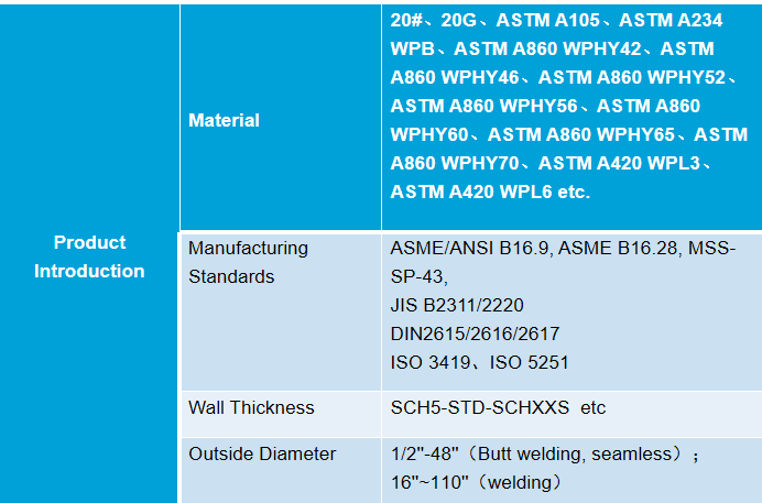
Product Introduction
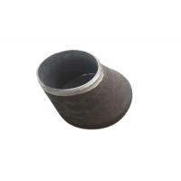
Concentric Reducer
**Product Overview**:
A concentric reducer is a type of pipe fitting designed to connect
two sections of piping or tubing that have different diameters. The
reducer is conical in shape and aligns the centerline of both
pipes, providing a smooth transition between the larger and smaller
pipe diameters. This ensures a consistent flow and minimizes
turbulence, making it ideal for liquid, gas, and vapor applications
where maintaining a uniform flow rate is crucial.
**Applications**:
Concentric reducers are widely used in various industries including
water treatment, petrochemical, oil and gas, power generation, and
processing plants. They are particularly useful in systems where
pressure integrity and fluid dynamics are critical, such as in
supply lines, cooling systems, and exhaust pipes.
**Key Features and Benefits**:
- **Smooth Fluid Flow**: The concentric design aligns the center
axes of the incoming and outgoing pipes, facilitating a seamless
flow. This alignment is crucial for minimizing turbulence and
reducing the risk of erosion within the piping system.
- **Pressure Management**: Concentric reducers are effective in
managing internal pressures in piping systems, especially where the
flow needs to be transitioned between different pipe sizes without
causing stress on the piping or equipment connections.
- **Versatile Material Options**: Available in a variety of
materials such as stainless steel, carbon steel, copper, and PVC,
concentric reducers can be tailored to meet the specific
requirements of different fluids and operating conditions.
- **Enhanced System Efficiency**: By providing a gradual transition
between different pipe sizes, these reducers optimize system
performance and efficiency. This design feature helps prevent
bottlenecks and pressure drops across the system.
- **Ease of Installation**: Concentric reducers are designed to be
easy to install and integrate into existing piping systems,
reducing downtime and labor costs associated with system upgrades
or maintenance.
- **Durability and Reliability**: Constructed to withstand high
pressures and extreme temperatures, concentric reducers offer
long-term reliability and durability, reducing the need for
frequent replacements and maintenance.
**Installation and Maintenance**:
Installation of concentric reducers should always be performed
following proper industry standards and guidelines to ensure
optimal performance and safety. Regular maintenance checks are
recommended to ensure that all connections are secure and that
there is no sign of wear or damage to the reducers. This
preventative approach helps in extending the life of the piping
system and reducing operational disruptions.
Concentric reducers are essential components in ensuring efficient and effective fluid flow in piping systems across various industrial applications, contributing significantly to system integrity and operational excellence.

SEAMLESS

WELD
ASME B16.9
| Nominal Size | Outside Diameter at Bevel | End to End | |
| DN | NPS | OD1×OD2 | H |
| 150×125 150×100 150×90 150×80 150×65 | 6×5 6×4 6×3 1/2 6×3 6×2 1/2 | 168.3×141.3 168.3×114.3 168.3×101.6 168.3×88.9 168.3×73.0 | 140 |
| 200×150 200×125 200×100 200×90 | 8×6 8×5 8×4 8×3 1/2 | 219.1×168.3 219.1×141.3 219.1×114.3 219.1×101.6 | 152 |
| 250×200 250×150 250×125 250×100 | 10 ×8 10×6 10×5 10×4 | 273.0×219.1 273.0×168.3 273.0×141.3 273.0×114.3 | 178 |
| 300×250 300×200 300×150 300×125 | 12×10 12 ×8 12×6 12×5 | 323.8×273.0 323.8×219.1 323.8×168.3 323.8×141.3 | 203 |
| 350×300 350×250 350×200 350×150 | 14×12 14×10 14×8 14×6 | 355.6×323.8 355.6×273.0 355.6×219.1 355.6×168.3 | 330 |
| 400×350 400×300 400×250 400×200 400×150 | 16×14 16×12 16×10 16×8 16×6 | 406.4×355.6 406.4×323.8 406.4×273.0 406.4×219.1 406.4×168.3 | 356 |
| 450×400 450×350 450×300 450×250 450×200 | 18×16 18×14 18×12 18×10 18×8 | 457.0×406.4 457.0×355.6 457.0×323.8 457.0×273.0 457.0×219.1 | 381 |
| 500×450 500×400 500×350 500×300 500×250 | 20×18 20×16 20×14 20×12 20×10 | 508.0×457.0 508.0×406.4 508.0×355.6 508.0×323.8 508.0×273.0 | 508 |
| 550×500 550×450 550×400 550×350 550×300 | 22 ×20 22×18 22×16 22×14 22×12 | 559.0×508.0 559.0×457.0 559.0×406.4 559.0×355.6 559.0×323.8 | 508 |
| BW CONCENTRIC &ECCENTRIC REDUCERS | |||
| Nominal Size | Outside Diameter at Bevel | End to End | |
| DN | NPS | OD1x OD2 | H |
| 600×550 600×500 600×450 600×400 600×350 600×300 | 24×22 24×20 24×18 24×16 24×14 24×12 | 610.0×559.0 610.0×508.0 610.0×457.0 610.0×406.4 610.0×355.6 610.0×323.8 | 508 |
| 650×600 650×550 650×500 650×450 650×400 650×350 | 26×24 26×22 26×20 26×18 26×16 26×14 | 660.0×610.0 6600×559.0 660.0 ×508.0 660.0×457.0 660.0×406.4 660.0×355.6 | 610 |
| 700×650 700×600 700×550 700×500 700×450 700×400 700×350 | 28×26 28×24 28×22 28×20 28×18 28×16 28×14 | 711.0×660.0 711.0×610.0 711.0×559.0 711.0×508.0 711.0×457.0 711.0×406.4 711.0×355.6 | 610 |
| 750×700 750×650 750×600 750×550 750×500 750×450 750×400 750×350 | 30×28 30×26 30×24 30×22 30×20 30×18 30×16 30×14 | 762.0×711.0 762.0×660.0 762.0×610.0 762.0×559.0 762.0×508.0 762.0×457.0 762.0×406.4 762.0×355.6 | 610 |
| 800×750 800×700 800×650 800×600 800×550 800×500 | 32×30 32×28 32×26 32×24 32×22 32×20 | 813.0×762.0 813.0×711.0 813.0×660.0 813.0×610.0 813.0×559.0 813.0×508.0 | 610 |
| 850×800 850×750 850×700 850×650 850×600 850×550 | 34×32 34×30 34×28 34×26 34×24 34×22 | 8640×813.0 864.0×762.0 864.0×711.0 864.0×660.0 864.0×610.0 864.0×559.0 | 610 |
| 900×850 900×800 900×750 900×700 900×650 900×600 900×550 | 36×34 36×32 36×30 36×28 36×26 36×24 36×22 | 914.0×864.0 914.0×813.0 914.0×762.0 914.0×711.0 914.0×660.0 914.0×610.0 914.0×559.0 | 610 |
| 950×900 950×850 950×800 950×750 950×700 950×650 950 ×600 | 38×36 38×34 38 ×32 38×30 38×28 38×26 38×24 | 9650×914.0 965.0×864.0 965.0×813.0 965.0×762.0 965.0×711.0 965.0×660.0 965.0×610.0 | 610 |
| 1000×950 1000×900 1000×850 1000×800 1000×750 1000×700 | 40×38 40×36 40×34 40×32 40×30 40×28 | 1016.0×965.0 1016.0×914.0 1016.0×864.0 1016.0×813.0 1016.0×762.0 1016.0×711.0 | 610 |
| 1050×1000 1050×950 1050×900 1050×850 1050×800 1050×750 1050×700 | 42×40 42×38 42×36 42×34 42×32 42×30 42×28 | 1067.0×1016.0 1067.0×965.0 1067.0×914.0 1067.0×864.0 1067.0×813.0 1067.0×762.0 1067.0×711.0 | 610 |
| 1100×1050 1100×1000 1100×950 1100×900 1100×850 1100×800 | 44×42 44×40 44×38 44×36 44×34 44×32 | 1118.0×1067.0 1118.0×1016.0 1118.0×965.0 1118.0×914.0 1118.0×864.0 1118.0×813.0 | 610 |
| 1150×1100 1150×1050 1150×1000 1150×950 1150×900 1150×850 | 46×44 46×42 46×40 46×38 46×36 46×34 | 1168.0×1118.0 1168.0×1067.0 1168.0×1016.0 1168.0×965.0 1168.0×914.0 1168.0×864.0 | 711 |
| 1200×1150 1200×1100 1200×1050 1200×1000 1200×950 1200×900 | 48×46 48×44 48×42 48×40 48×38 48×36 | 1219.0×1168.0 1219.0×1118.0 1219.0×1067.0 1219.0×1016.0 1219.0×965.0 1219.0×914.0 | 711 |
| 1300×1200 1300×1150 1300×1100 1300×1050 1300×1000 | 52×48 52×46 52×44 52×42 52×40 | 1321.0×1219.0 1321.0×1168.0 1321.0×1118.0 1321.0×1067.0 1321.0×1016.0 | 711 |
| 1400×1300 1400×1200 1400×1100 1400×1000 | 56×52 56×48 56×44 56×40 | 1422.0×1321.0 1422.0×1219.0 1422.0×1118.0 1422.0×1016.0 | 711 |
| 1500×1400 1500×1300 1500×1200 1500×1100 | 60×56 60×52 60×48 60×44 | 1524.0×1422.0 1524.0×1321.0 1524.0×1219.0 1524.0×1118.0 | 711 |
Notes: l Besides ASME, European standard EN, German standard DIN, Japanese standard (JIS), etc.are also applied.
| |||