|
|
[China]

Trade Verify
Address: Plant NO.1,No.28,YinzhuRoad,New District,Suzhou,Jiangsu,China
Contact name:Barry Wang

Suzhou Ephood Automation Equipment Co., Ltd. |
|
Verified Suppliers
|
|
|
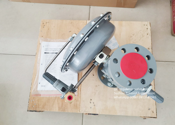
High Flow Rate Fisher Gas Regulator 1098-EGR Pressure Reducing Regulator
For Corrosive Environments And Oxygen Service
Emerson Group Fisher Brand Make Type 1098-EGR Pressure Reducing Regulators
Fisher Type 1098-EGR pressure gas regulator provide economical and accurate pressure control in a wide variety of applications.
Natural gas distribution systems; fuel gas supply to industrial boilers, furnaces, ovens, and mixers; and large commercial / industrial establishments such as shopping centers and schools. They are also used in plant air service and in liquid service.
Table 1. Outlet Pressure Ranges and Spring Selection
| Outlet Pressure Range (PSI/BAR) | Spring Part Number | Spring Color |
| 3 to 15(0,21 to 1,03) 3 to 20(0,21 to 1,38) 5 to 35(0,34 to 2,41) 30 to 60(2,07 to 4,14) 35 to 100(2,41 to 6,90) 80 to 150(5,52 to 10,3) | 1D892327022 1D751527022 1D665927022 1D745527142 1E543627142 1P901327142 | Red Silver Blue Green Yellow Brown |
| 1. All springs can be backed off to 0 psig (0 bar). For the highest
capacity and most accurate control, use the lowest-range spring
that can be adjusted to the required setpoint. 2. C Cannot be used in anhydrous ammonia (NH3) applications. | ||
Features
Versatility
Body Side Connection
Easy Maintenance
UL Listed
Specifications
Body Size and End Connection Style
End: 1/2-inch NPT
Gauge Outlet: 1/4-inch NPT
Maximum Inlet Pressure
250psi /17.2Bar
Spring Range
5~35psig (0.34~2.41bar)
Pressure Registration
Internal
Temperature Capabilities
-20º to 150ºF / -29º to 66ºC
1. Use qualified personnel when installing, operating, and maintaining these regulators. Before installation inspect for damage.
Make sure there is not any foreign material in the regulator and all tubing and piping are clean and unobstructed.
2. If installing the regulator at an outside location, point the spring case vent in the downward direction to protect it from getting
plugged or from collecting moisture, corrosive chemicals, or other foreign materials. Spring case vent orientation may be changed
by rotating the spring case with respect to the regulator body.
3. Install the regulator so that flow is from the IN to OUT connection as marked on the regulator body.
4. To remotely vent the spring case, remove the screen, if present, and connect 1/4-inch NPT piping or tubing to the spring case
connection. The piping or tubing should vent the spring case to a safe location, have as few bends as possible, and have a screened
vent on its exhaust end that is weather resistant and always pointed in the downward direction.
5. Like most regulators, 64 Series regulators have outlet pressure ratings lower than inlet pressure ratings. Although types with
internal relief include limited downstream overpressure protection, all types may require additional relief protection for some service
conditions if the actual inlet pressure can exceed the regulator outlet pressure rating or the pressure ratings of any downstream
equipment. Inspect a regulator periodically and after any overpressure condition.
6. Each regulator is factory-set for the pressure setting specified on the order. If no setting is specified, outlet pressure is
factory-set at the midrange of the control spring.