ISO2339/DIN EN 22339 Stainless Steel SUS304 Plain Taper Pins Φ6-Φ12
Features
- Tapered Design: Taper pins typically have a taper ratio of 1:50, which allows for
the redirection of lateral forces through friction, resulting in
excellent self-locking capabilities.
- High Precision: Taper pins offer superior positioning accuracy compared to
cylindrical pins, and repeated assembly and disassembly in the same
hole do not affect the positioning accuracy or connection
reliability.
- Easy Installation and Removal: Due to their tapered design and self-locking properties, taper
pins are relatively easy to install and remove.
Advantages
- Excellent Self-Locking: The tapered design and friction forces enable taper pins to
maintain a stable connection without the need for additional
locking devices.
- High Precision and Reliability: The high-precision design ensures consistent performance in
various applications, and repeated assembly and disassembly do not
compromise positioning accuracy or connection reliability.
- Wide Applicability: Due to their characteristics, taper pins are suitable for various
scenarios requiring high-precision positioning and connection.
Applications
- Mechanical Engineering: In mechanical engineering, taper pins are commonly used for
components requiring precise positioning and connection, such as
bearings and gears.
- Mold Manufacturing: In mold manufacturing, taper pins are utilized to secure various
mold parts, ensuring mold precision and stability.
- Automated Equipment: Taper pins are also employed in automated equipment for
components requiring high-precision connection and positioning.
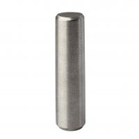
Please note that while ISO 2339 and DIN EN 22339 are common
standards for taper pins, they may differ in terms of product
length specifications and other details. Therefore, selection and
use should be based on specific application requirements and
scenarios.
![](http://img.everychina.com/nimg/fd/cc/a223eae7aac6b4dfa9c1c8d4087b.jpg)
Nominal Diameter | Φ0.6 | Φ0.8 | Φ1 | Φ1.2 | Φ1.5 | Φ2 | Φ2.5 |
d |
d | max=nominal size (h10) | 0.6 | 0.8 | 1 | 1.2 | 1.5 | 2 | 2.5 |
min | 0.56 | 0.76 | 0.96 | 1.16 | 1.46 | 1.96 | 2.46 |
a | ≈ | 0.08 | 0.1 | 0.12 | 0.16 | 0.2 | 0.25 | 0.3 |
Nominal Diameter | Φ3 | Φ4 | Φ5 | Φ6 | Φ8 | Φ10 | Φ12 |
d |
d | max=nominal size (h10) | 3 | 4 | 5 | 6 | 8 | 10 | 12 |
min | 2.96 | 3.952 | 4.952 | 5.952 | 7.942 | 9.942 | 11.93 |
a | ≈ | 0.4 | 0.5 | 0.63 | 0.8 | 1 | 1.2 | 1.6 |
Nominal Diameter | Φ16 | Φ20 | Φ25 | Φ30 | Φ40 | Φ50 | |
d | |
d | max=nominal size (h10) | 16 | 20 | 25 | 30 | 40 | 50 | |
min | 15.93 | 19.916 | 24.916 | 29.916 | 39.9 | 49.9 | |
a | ≈ | 2 | 2.5 | 3 | 4 | 5 | 6.3 | |