

Active Member
|
[China]

Address: No.680 Tingyi Road, Tinglin Industrial Park, Jinshan District, Shanghai, 201505, China
Contact name:Caroline Wang

Shanghai Beyond Machinery Co., Ltd |
|
|
Technical Data
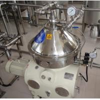
2.2.1 Structure
The drum is the most important components of separator, as shown in
the figure, the drum
body is fixed together with drum cover by main lock ring and
equipped with the distributor and
the disk plate set. The top of drum cover and the centrifugal pump
cover form a light-phase
pump chamber. The drum body is also equipped with piston and small
valve structure inside,
and the drum and piton bottom form the sealing water chamber.
2.2.2 The function of separation
The flow of the liquid in the drum:
Materials enter the distributor from the upper feed inlet and
through the feeding tube and are
distributed to the discs set for separation, the solid particles
move along the disc and towards
the drum wall. During deslagging, the sludge is discharged from the
sludge outlet; the
clear-liquid-phase enters the clear-liquid-phase pump chamber
through the clear-liquid-phase
movement along the disk around the drum center and discharged out
by the clear-liquid-phase
centripetal pump from the clear-liquid-phase outlet.
2.2.3 Function of residue removal
Normal separation:
The valve (1) is opened, the bottom of the piston (a) fill up with
water, and due to the effect of
centrifugal force, the water at the bottom of the piston produces
very high hydraulic pressure
F2 on the piston, which is higher than the hydraulic pressure F1
produced by the substances in
the inner cavity of the drum, the piston thus is driven to push
against the seal ring (nylon) (b),
and it is ensured that the process of separation is carried out
under the conditions in which the
inner cavity of the drum is airtight. The valve core (c) ensures
that the nylon valve (d) doesn’t
leak by the centrifugal force F generated by itself. As the feed
valve is opened, the separation
liquid continuously enters the drum for separating, and thus the
solid particles are separated
from the separating liquid, and accumulated on the drum wall while
the clear liquid phase is
discharged from the centripetal pump.


