

Active Member
|
[China]

Contact name:

Shijiazhuang Shiza Pump Industry Co.,Ltd. |
|
|
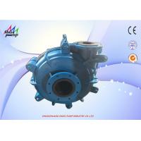
8 Inches Suction Slurry Pump , Double Casing Industrial Sludge Pump
Main introduction of slurry pump
12/10ST- is double casing structure,double casing structure namely pump body, pump cover with replaceable wear-resistant metal lining (including impeller, sheath, sheath, etc.). 8 / 6 - R slurry pump (suction 8 inch discharge 6 inch) double pump shell pump body, pump cover according to the working pressure using gray iron or ductile iron manufacturing, vertical open, bolted connection. The pump body has a stop port connected with the bracket by bolts. The pump outlet can be rotated by eight angles. The front and rear cover plates of the impeller have back blades to reduce leakage and improve the service life of the pump.
Model meaning
8 / 6 E - R
8-------Suction diameter(Inch)
6-------Discharge diameter(Inch)
E-------Support type
------Slurry pump type
R--------Natural Rubber
Specifications
| Pump Model | 8 / 6 E - R |
| Allowable Max.Power | 120 kw |
| Capacity | 324 - 720 m³/h |
| Head | 7 - 49 m |
| Speed | 400 - 1000 r/min |
| Meax.Eff. | 65% |
| NPSH | 5 - 10 m |
| Impeller Diameter | 510 mm |
8 / 6 E - R start: Check the entire unit as follows before starting.
(1) The pump should be placed on a firm foundation to withstand the
full weight of the pump to eliminate vibration and tighten all
anchor bolts.
(2) Pipes and valves should be supported separately. @Slurry pump
8/6E-R There is a gasket at the pump flange. When tightening the
coupling bolt, please pay attention to the pump metal lining is
higher than the flange. At this time, the bolt should not be
tightened too much to avoid damage to the gasket.
(3) Rotate the shaft by hand according to the direction of rotation
of the pump. The shaft should be able to drive the impeller to
rotate, and there should be no friction. Otherwise, the impeller
clearance should be adjusted.
(4) Check the steering of the motor. Make sure that the pump
rotates in the direction of the arrow marked on the pump body. Note
that the pump is not allowed to rotate in the opposite direction,
otherwise the impeller thread will trip, causing damage to the
pump.
(5) When the transmission is directly connected, the pump shaft and
the motor shaft should be accurately centered. When the belt is
driven, the pump shaft and the motor shaft should be parallel, and
the position of the sheave should be adjusted so as to be
perpendicular to the groove to avoid severe vibration and wear.
(6) A detachable short pipe shall be installed at the suction pipe
of the pump. The length shall be sufficient to disassemble the pump
cover and replace the wearing parts to facilitate the inspection of
the pump. The length of each pump is shown in the external
dimensions of each pump.
(7) Shaft seal inspection: The pump of the auxiliary impeller shaft
seal has different sealing structure. Therefore, when the oil
pressure cup is equipped with oil cup, it is necessary to add
grease through the oil cup. The grease is recommended to be
lubricated with calcium and sodium. fat.
Typical Applications:
Ash Handling
Cyclone Feeds
Pulp and Paper
Abrasive Slurries
Coal Preparation
Mineral Processing
Aggregate Processing
Construction Design

Shaft Seal Module Design

Performance table
| MODEL | ALLOWABLE MATING | MATERIAL | CLEAN WATER PERFORANCE | IMPELLER | |||||||
| MAX.POWER | LINER | IMPELLER | Q Capacity | H Head | Speed | Max. Eff. | NPSH | VANES NO. | IMPELLER DIA | ||
| (KW) | m3/h | L/s | (m) | n(r/min) | (%) | (m) | (mm) | ||||
| 1.5/B- | 15 | M | M | 12.6-28.8 | 3.5-8 | 6-68 | 1200-3800 | 40 | 2--4 | 5 | 152 |
| RU | RU | 10.8-25.2 | 3--7 | 7-52 | 1400-3400 | 30 | 3 | ||||
| 1/1.5B- | 15 | M | M | 16.2-34.2 | 4.5-9.5 | 25-92 | 1400-2200 | 20 | 2-5.5 | 5 | 330 |
| 2/1.5B- | 15 | M | M | 32.4-72 | 9--20 | 6-58 | 1200-3200 | 45 | 3.5-8 | 5 | 184 |
| RU | RU | 25.2-54 | 7--15 | 5.5--41 | 1000-2600 | 50 | 2.5-5 | 5 | 178 | ||
| 3/2C- | 30 | M | M | 39.6-86.4 | 11--24 | 12-64 | 1300-2700 | 55 | 4--6 | 5 | 214 |
| RU | RU | 36-75.6 | 10--21 | 13-46 | 1300-2300 | 60 | 2--4 | 5 | 213 | ||
| 3/2D-HH | 60 | M | M | 68.4-136.8 | 19-38 | 25-87 | 850-1400 | 47 | 3-7.5 | 5 | 457 |
| 4/3C- | 30 | M | M | 86.4-198 | 24-55 | 9-52 | 1000-2200 | 71 | 4--6 | 5 | 245 |
| RU | RU | 79.2-180 | 22-50 | 5-34.5 | 800-1800 | 59 | 3--5 | ||||
| 4/3E-HH | 120 | M | M | 126-252 | 35-70 | 12-97 | 600-1400 | 50 | 2--5 | 5 | 508 |
| 6/D- | 60 | M | M | 162-360 | 40-100 | 12-56 | 800-1550 | 65 | 5--8 | 5 | 365 |
| RU | RU | 144-324 | 40-90 | 12-45 | 800-1350 | 65 | 3--5 | 5 | 365 | ||
| 6/4S-HH | 560 | M | M | 324-720 | 90-200 | 30-118 | 600-1000 | 64 | 3--8 | 5 | 711 |
| 6S-HH | 560 | M | M | 468-1008 | 130-280 | 20-94 | 500-1000 | 65 | 4--12 | 5 | 711 |
| 8/6E- | 300 | M | M | 360-828 | 100-230 | 10-61 | 500-1140 | 72 | 2--9 | 5 | 510 |
| RU | RU | 324-720 | 90-200 | 7-49 | 400-1000 | 65 | 5--10 | 5 | 510 | ||
| 10/8E-M | 120 | M | M | 666-1440 | 185-400 | 14-60 | 600-1100 | 73 | 4--10 | 5 | 549 |
| 10/8ST- | 560 | M | M | 612-1368 | 170-380 | 11-61 | 400-850 | 71 | 4--10 | 5 | 686 |
| RU | RU | 540-1118 | 150-330 | 12-50 | 400-750 | 75 | 4--12 | ||||
| 12/10ST- | 560 | M | M | 936-1980 | 260-550 | 7-68 | 300-800 | 82 | 6 | 5 | 762 |
| RU | RU | 720-1620 | 200-450 | 7-45 | 300-650 | 80 | 2.5-7.5 | ||||
| 14/12ST- | 560 | M | M | 1260-2772 | 350-770 | 13-63 | 300-600 | 77 | 3--08 | 5 | 965 |
| RU | RU | 1152-2520 | 320-700 | 13-44 | 300-500 | 79 | 3--10 | ||||
| 16/14TU- | 1200 | M | M | 1368-3060 | 380-850 | 11-63 | 250-550 | 79 | 4--10 | 5 | 1067 |
| 20/18TU- | 1200 | M | M | 2520-5400 | 700-1500 | 13-57 | 200-400 | 85 | 5--10 | 5 | 1370 |


