Active Member
|
[China]

Address: No.119 JianShe Road,luoyang city 471000,China
Contact name:Dave-Lee

LUOYANG MONTON BEARING SCIENCE & TECHNOLOGY CO.,LTD. |
|
|
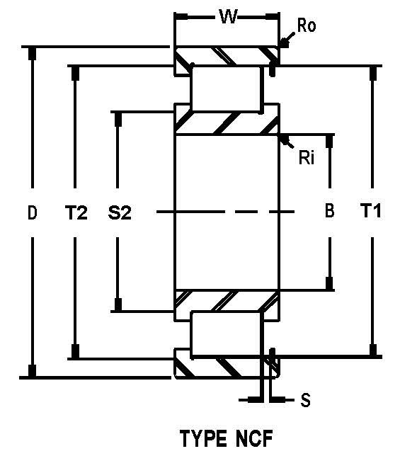
NCF
These are the most common full complement cylindrical roller
bearings. The inner ring has two flanges, the outer ring has one
flange on one side and a snap ring, which keeps the bearing
assembled on the other side. NCF bearings are able to carry axial
load from one side a they are able to accommodate certain minor
axial displacement of the shaft. The
permissible values for this displacement are in the dimension
tables.
Double row full complement cylindrical roller bearings are all
supplied with a lubrication groove with holes in the outer ring,
which enables full lubrication access into the rolling space of
each row of cylindrical rollers. The inner ring of the NNC, NNCL
and NNCF design has three guiding flanges to ensure guiding
accuracy of cylindrical rollers. They differentiate by the number
of guiding flanges and snap rings in the outer ring. These
components stop the rolling elements from falling out.
NNC
One side of outer ring is equipped with guiding flange, the other
side has snap ring to keep the cylindrical rollers in place. These
bearings can carry the axial load in both directions.
NNCL
NNCL bearings have the flangeless outer ring therefore certain
axial bearing rings displacement against each other is
accommodated.
NNCF
The outer ring has one flange and one snap ring. These components
accommodate axial load transfer in one direction and also certain
shaft displacement of the housing.
NNF
NNF bearings are produced with guiding flanges in the two-piece
inner ring, which is held together by a retaining ring. The outer
ring has a guiding flange. These bearings can also carry the axial
load in both directions and as per bigger distance between
individual rows of cylindrical rollers, they can transfer a tilting
moments.
The outer ring of an NNF bearing is 1 mm narrower than the inner
ring and has two snap ring grooves. These bearings are supplied as
standard with seals on both sides and the inner space is filled
with grease to enable the bearing operation in standard working
conditions up to 110°C.

| d | 280 | mm | |
| D | 380 | mm | |
| B | 60 | mm | |
| d1 | ≈ | 314 | mm |
| D1 | ≈ | 348 | mm |
| E | 359.1 | mm | |
| s | max. | 3 | mm |
| r1,2 | min. | 2.1 | mm |
| r3,4 | min. | 1.5 | mm |

| da | min. | 291 | mm |
| das | 309 | mm | |
| Da | max. | 368 | mm |
| Db | max. | 370 | mm |
| ra | max. | 2 | mm |
| rb | max. | 1.5 | mm |
| Basic dynamic load rating | C | 880 | kN | |
| Basic static load rating | C0 | 1730 | kN | |
| Fatigue load limit | Pu | 166 | kN | |
| Reference speed | 700 | r/min | ||
| Limiting speed | 900 | r/min | ||
| Calculation factor | kr | 0.2 | ||
| Calculation factor | e | 0.3 | ||
| Calculation factor | Y | 0.4 |
| Mass bearing | 19.6 | kg |
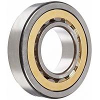
Single Row Full Complement Cylindrical Roller bearings are designed
for heavier loads than same dimensioned counterparts using a cage.
This added load carrying capacity is because of the increased
number of rollers and is a trade- off for the lower speed rating.
These ISO metric dimensioned bearings are supplied with C3 Internal
Radial Clearance unless specified. They are industry
interchangeable with like size numbered bearings and are used in
such applications as accumulator sheaves, gearboxes and walking
beam furnace eccentrics.