

Active Member
|
[China]

Address: room 602, NO.26, Lane362, Moyu road,Anting town, jiading district, Shanghai, 201805
Contact name:Lilith

Shanghai Qi Pang Industrial Co., Ltd. |
|
|
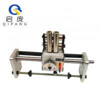
High accuracy Rolling Ring Drive traverse unit Used In Winding Machine
Type of the High accuracy Rolling Ring Drive traverse unit Used In Winding Machine:
1, GP3-30A:one rolling ring drive.
2, GP3-30B:one rolling ring drive with guide roller or guide wheel.
3, GP3-30C:B with accessories, such as shaft ,guide wheel ,bearing block ,baffle and so on.
| The Parameter List (Rolling Ring Drives) | |||
| Model No: | Linear Pitch mm/r | Axial Thrust kg | Weight kg |
| GP3-15 | 1~11 | 11(110N)KG | 1.2 |
| GP4-15 | 1~11 | 22(220N)KG | 1.5 |
| GP3-20 | 1~16 | 16(160N)KG | 2.5 |
| GP4-20 | 1~16 | 32(320N)KG | 3 |
| GP3-22 | 1~16 | 16(160N)KG | 2.5 |
| GP4-22 | 1~16 | 32(320N)KG | 3 |
| GP3-25 | 1~25 | 26(260N)KG | 3 |
| GP3-30 | 1~25 | 26(260N)KG | 3 |
| GP4-30 | 1~25 | 52(520N)KG | 3.7 |
| GP3-40 | 1~32 | 42(420N)KG | 10 |
| GP4-40 | 1~32 | 84(840N)KG | 13 |
| GP3-50 | 2~40 | 70(700N)KG | 20 |
| GP4-50 | 2~40 | 140(1400N)KG | 38 |
| GP3-60 | 2~48 | 100(1000N)KG | 40 |
| GP4-60 | 2~48 | 200(2000N)KG | 45 |


Installation and Debugging:
Release Lever There are two positions, i.e. the working position “1” and the releasing position “0”. When the lever sits at the working position, the bearings above it are at the lifting position and apply pressure to the Smooth Shaft and so make the Traverse Drive generate the thrust force. When the lever sits at the Releasing position, the bearings above it are at the falling position and by pushing with hands you can make the Traverse Drive slide freely on the Smooth Shaft. Before install the Smooth Shaft, pull the Release Lever and check if the bearings can be moved up and down.
Mounting the Smooth Shaft By putting the Release Lever at the released position “0” and adjusting the sheathes at the both sides of the Traverse Drive you can install the Shaft into the Traverse Drive, and then pull the Release Lever to the Working position”1”.
Rotation Speed of Shaft The take-up bobbin speed shall be higher than the shaft speed of the traverse drive. The speed ratio available ranges from 5:1 to 1:1. If the wire size is small the ratio will be large and if the wire size is large the ratio will be small.
Pitch Adjustment The scale values 1-10 on the dial are the adjustment range of pitches, and not the numeric value of pitch. The pitch is matched to the thickness of the wire/cable. When the Indicator is at the left of the Scale Dial, the Traverse Drive dwells on the shaft without any movement. In addition, the adjustment should not be made to the maximum pitch position. When adjustment is made the Indicator shall be disengaged completely from the Serrated Scale Dial.
Mounting the Wire Guide Pulley/Roller When mounting the wire part special care should be taken not to turn the screw too deeply into the box, in order to avoid influence the normal working conditions of the internal mechanism.
Traverse Travel Adjust the positions of two reversal end stops on the lead screw to make the travel match the position and length of the take-up bobbin.
High accuracy Rolling Ring Drive traverse unit Used In Winding Machine


