

Active Member
|
[China]

Address: No.337,Kaichuang Road,Baitawang Industrial Distrit, Beibaixiang Town,Yueqing City,Zhejiang Province,China
Contact name:

Wenzhou Ginri Power Automation Co., Ltd. |
|
|
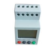
GINRI SVR1000 Single Phase Voltage Relay Adjustable Over Under
Voltage Protection Monitor Relay with LCD display
The Features of SVR10000
-- Powered by the measuring circuit
-- Built-in LCD and keypad afford a precise,digital setting
-- Compact modular 43mm housing
-- Adjustable over- and undervoltage threshold
-- Independent adjustable delay time for overvoltage, undervoltage
-- 1 CO & 1NC contacts
-- Fault recording with last 3 faults
♦ Protective Functions
-- Overvoltage
-- Undervoltage
♦ Typical Applications
• Pumps • Fans
• Blowers • Motors
• Compressors
♦ Approvals
• CE • CCC
♦ Technical data
| Model | SVR1000/D12 | SVR1000/AD48 | SVR1000/AD220 | ||
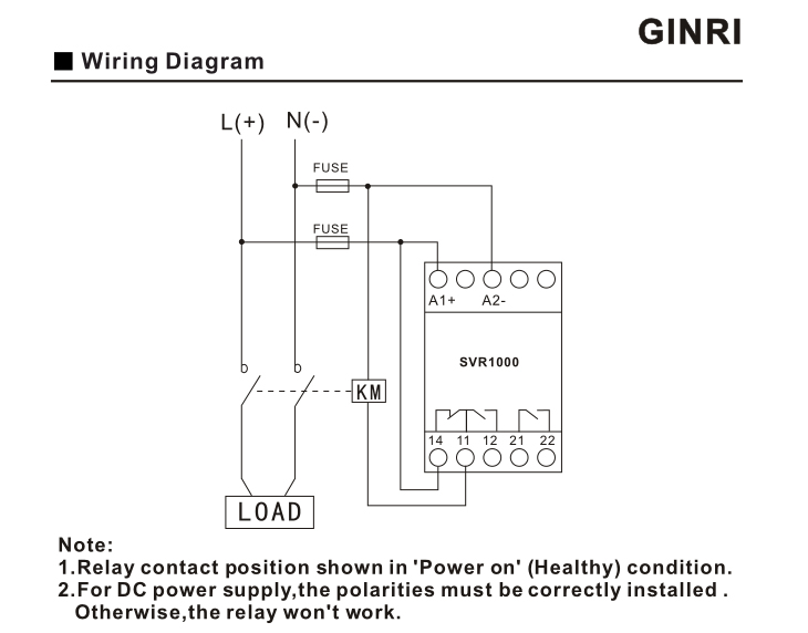
| Measuring circuit | A1+,A2- | ||||
| Rated voltage | DC 12V | AC/DC 24~48V,50/60Hz | AC/DC | ||
| Monitoring functions | overvolatege, undervoltage | ||||
| Overvoltage setting range | DC | AC/DC 20.0~80.0V adjustable | AC/DC | ||
| Undervoltage setting range | DC | AC/DC 20.0~80.0V adjustable | AC/DC | ||
| Voltage hysteresis | 0.1~6.0V adjustable | 0.1~30.0V adjustable | 1.0~90.0V adjustable | ||
Delay time for overvoltage | 0.1-999s adjustable | ||||
| Reset mode | Manual/ Automatic/Automatic with power-on delay | ||||
| Delay time for reset | 0.1-999s adjustable | ||||
| Indicators | LCD indicating voltage,operationand fault status | ||||
| Output contacts | 1 CO & 1NC | ||||
| Contact capacity | 6A ,250VAC | ||||
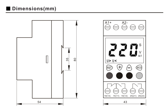
| Dimensions (H x W x D) | 80×43×54mm | ||||
| Mounting | DIN rail | ||||
The reason of used the over under voltage relay
Take the electric equipment on the line as an example. If the
electric energy can't keep up, the voltage will drop very much.
According to the formula: P=U*I, U becomes smaller, I will become
larger, and U is smaller than the current I on the line. It will be
bigger.
For example, when U starts, it is U1. At this time, I=I1=P/U1. If
the power can't keep up at this time, because the power consumption
P needs to be used, the U drops to 0.5U1. Current:
I=P/U=P/(0.5U1)=2*(P/U1)=2I1
In other words, if the voltage drops by half, the current will
double.
In this case, the problem comes. According to the well-known Joule
law: heat quantity Q=I*R*T
The resistance value R of any device on the line is certain. If the
previous line heat is Q1=I1*R*T, the voltage U changes to 0.5U1,
the current I is 2I1, and the line heats up Q2= I*R* T = (2I1) * R
* T = 4 * I1 * R * T = 4Q1, that is, if the voltage drops by half,
the heat generated per unit time will become four times the
previous one.
It can be seen that the change of the heat per unit time of the
device on the line is inversely proportional to the square of the
change of the line voltage. Therefore, the more the voltage drops,
the greater the heat generated by the device on the line, and the
heat accumulation of the device on the line exceeds the thermal
diffusion. The speed of the device will become higher and higher,
which may cause accidents such as fire.
Therefore, it is necessary to set a threshold voltage for the line.
When the line voltage drops to this threshold voltage, the line is
cut off by a relay protection device or the like, thereby ensuring
that the device on the entire circuit does not burn out. This is
called undervoltage protection.


