
|
|
[China]

Trade Verify
Address: 4F, Building 5, Dongluyang Industrial ,Park, No. 4, Tengfeng 4th Road, Fuyong Phoenix Third, Industrial Zone, Baoan District, Shenzhen China
Contact name:Terry

Shenzhen Veikong Electric Co., Ltd. |
|
Verified Suppliers
|
|
|
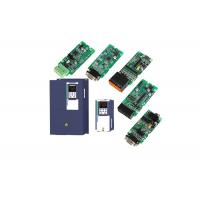
22kw 30hp variable frequency drive VFD AC DRIVE INVERTERS vector control
Product Advantage
1. Optimized external installation and internal structure and independent air flue design, fully enclosed electrical space design.
2. Output automatic voltage regulation function (AVR),
automatically adjust the output pulse width to eliminate the
influence of the grid change on load.
3. Built-in PID regulation function to facilitate the realization
of closed loop control of the temperature, pressure and flow, and
reduce the cost of the control system.
4. Standard MODBUS communication protocol. Easy to achieve the
communication between PLC, IPC and other industrial equipments.
| Item | Specifiation | |
| Input | Inuput Voltage | 1phase/3phase 220V:200V~240V 3 phase 380V-480V:380V~480V |
| Allowed Voltage fluctuation range | -15%~10% | |
| Input frequency | 50Hz / 60Hz,fluctuation less than 5% | |
| Output | Output Voltage | 3phase:0~input voltage |
| Overload capacity | General purpose application:60S for 150% of the rated current Light load application:60S for 120% of the rated current | |
| Control | Control mode | V/f control Sensorless flux vector control without PG card(SVC) Sensor speed flux vector control with PG card (VC) |
| Operating mode | Speed control,Torque control(SVC and VC) | |
| Speed range | 1:100 (V/f) 1:200( SVC) 1:1000 (VC) | |
| Speed control accuracy | ±0.5% (V/f) ±0.2% (SVC) ±0.02% (VC) | |
| Speed response | 5Hz(V/f) 20Hz(SVC) 50Hz(VC) | |
| frequency range | 0.00~600.00Hz(V/f) 0.00~200.00Hz(SVC) 0.00~400.00Hz(VC) | |
| Input frequency resolution | Digital setting: 0.01 Hz Analog setting: maximum frequency x 0.1% | |
| Startup torque | 150%/0.5Hz(V/f) 180%/0.25Hz(SVC) 200%/0Hz(VC) | |
| Torque control accuracy | SVC:within 5Hz10%,above 5Hz5% VC:3.0% | |
| V/f curve | V / f curve type: straight line, multipoint, power function, V / f separation; Torque boost support: Automatic torque boost (factory setting), manual torque boost | |
| Frequency giving ramp | Support linear and S curve acceleration and deceleration; 4 groups of acceleration and deceleration time, setting range 0.00s ~ 60000s | |
| DC bus voltage control | Overvoltage stall control: limit the power generation of the motor by adjusting the output frequency to avoid skipping the voltage fault;
Undervoltage stall control: control the power consumption of the motor by adjusting the output frequency to avoid yaw failure
VdcMax Control: Limit the amount of power generated by the motor by adjusting the output frequency to avoid over-voltage trip; VdcMin control: Control the power consumption of the motor by adjusting the output frequency, to avoid jump undervoltage fault | |
| Carrier frequency | 1kHz~12kHz(Varies depending on the type) | |
| Startup method | Direct start (can be superimposed DC brake); speed tracking start | |
| Stop method | Deceleration stop (can be superimposed DC braking); free to stop | |
| Maincontrol function | Jog control, droop control, up to 16-speed operation, dangerous speed avoidance, swing frequency operation, acceleration and deceleration time switching, VF separation, over excitation braking, process PID control, sleep and wake-up function, built-in simple PLC logic, virtual Input and output terminals, built-in delay unit, built-in comparison unit and logic unit, parameter backup and recovery, perfect fault record,fault reset, two groups of motor parametersfreeswitching, software swap output wiring, terminals UP / DOWN | |
| Function | Keypad | LED Digital keyboard and LCD keypad(option) |
| Communication | Standard: MODBUS communication CAN OPEN AND PROFINET( IN DEVELOPMENT) | |
| PG card | Incremental Encoder Interface Card (Differential Output and Open Collector), Rotary transformer Card | |
| Input terminal | Standard: 5 digital input terminals, one of which supports high-speed pulse input up to 50kHz; 2 analog input terminals, support 0 ~ 10V voltage input or 0 ~ 20mA current input; Option card: 4 digital input terminals 2 analog input terminals.support-10V-+10V voltage input | |
| Output terminal | standard: 1 digital output terminal; 1 high-speed pulse output terminal (open collector type), support 0 ~ 50kHz square wave signal output; 1 relay output terminal(second relay is an option ) 2 analog output terminals, support 0 ~ 20mA current output or 0 ~ 10V voltage output; Option card: 4 digital output terminals | |
| Protection | Refer to Chapter 6 "Troubleshooting and Countermeasures" for the protection function | |
| Environment | Installation location | Indoor, no direct sunlight, dust, corrosive gas, combustible gas, oil smoke, vapor, drip or salt. |
| Altitude | 0-3000m.inverter will be derated if altitude higher than1000m and rated output current will reduce by 1% if altitude increase by 100m | |
| Ambient temperature | -10°C~ +40°C,maximum 50°C (derated if the ambient temperature is between 40°C and 50°C)Rated output current decrease by 1.5% if temperature increase by 1°C | |
| Humidity | Less than 95%RH, without condensing | |
| Vibration | Less than 5.9 m/s2 (0.6 g) | |
| Storage temperature | -20°C ~ +60°C | |
| Others | Installation | Wall-mounted, floor-controlled cabinet, transmural |
| Protection level | IP20 | |
| cooling method | Forced air cooling | |
| EMC | CE ROHS | Internal EMC filter Complies with EN61800-3 Category C3 3rd Environment |
Replace famous brands vfd in general application.

VEIKONG VD500 application picture:


| 23 Group Drive protection function setting | ||||
| P23.00 | DC Bus voltage control option | Ø Unit’digit :Overvoltage stall control Ø The over-voltage stall function limits the amount of power
generated by the motor by extending the deceleration time or even
increasing the speed, avoiding over-voltage on the DC side and
reporting over-voltage faults Ø The undervoltage stall function reduces the motor power consumption or reduces the power consumption of the motor or turns it into a power generation operation to avoid the undervoltage fault on the DC side. Ø The undervoltage stall function is used when the input power supply quality is poor (the power supply voltage fluctuates downward or the sporadic short power is suspended), and it is necessary to keep the inverter running as much as possible. | 01 | ★ |
| P23.01 | Overvoltage stall threshold | 220V Level: 320V~400V 380V Level: 540V~800V 480V Level:650V~950V | Depend | ★ |
| P23.02 | Undervoltage threshold | 220V level: 160V~300V 380V level: 350V~520V 480V level: 400V~650V | Depend | ★ |
| P23.03 | Overvoltage stall ratio | 0~10.0 | 1.0 | ☆ |
| P23.04 | Undervoltage stall ratio | 0~20.0 | 4.0 | ☆ |
| P23.05 | Undervoltage trip threshold | 220V Level:160V~300V 380V Level:350V~520V 480V Level:400V~650V | Depend | ★ |
| P23.06 | Undervoltage fault detecting time | 0.0s~30.0s | 1.0s | ☆ |
| P23.07 | Rapid current limit | 0:Disabled 1:Enabled | 1 | ★ |
| P23.10 | Over-speed detection value | 0.0%~120.0% maximum frequency | 120.0% | ☆ |
| P23.11 | Over-speed detection time | 0.0s~30.0s0.:shielding | 1.0s | ☆ |
| P23.12 | Detection value of too large speed deviation | 0.0%~100.0%(motor rated frequency) | 20.0% | ☆ |
| P23.13 | Detection value of too large speed deviation | 0.0s~30.0s 0.0:shielding | 0.0s | ☆ |
| P23.14 | Input phase loss detection time | 0.0s~30.0s 0.0:forbidden | 8.0s | ☆ |
| P23.15 | Output phase loss inbalance detecting | 0%~100% | 30% | ☆ |
| P23.18 | Fault protection action selection 1 | Unit’s digit : input phase loss 0: coast to stop 1: Emergent stop 2: Stop as per stop mode 3: Continue to Run Ten’unit: user self-defined fault 1 same as Unit’s digit Hundred’unit: user self-defined fault 2 same as Unit’digit Thousand’s unit: communication fault same as unit’s digit | 0000 | ☆ |
| P23.19 | Fault protection action selection 2 | Unit’s digit: motor overload 0: Coast to stop 1: Emergent stop 2: Stop as per stop mode 3: Continue to run Ten’unit: motor overheat same as unit’digit Hundred’unit: too large speed deviation same as unit’digit Thousand’s unit: motor over speed same as Unit’digit | 0000 | ☆ |
| P23.20 | Fault protection action selection 3 | Unit’s digit: PID feedback lost during running 0: Coast to stop 1: Fast stop 2: Stop as per stop mode 3: Continue to run Ten’unit: Reserved same as unit’digit Hundred’unit: reserved same as unit’digit thousand’unit: reserved same as unit’digit | 0000 | ☆ |
| P23.21 | Fault protection action selection 4 | Unit’s digit: output phase loss 0: Coast to stop 1: Fast stop 2: Stop as per stop mode Ten’unit: EEPROM fault 0: Coast to stop 1: Fast stop 2: Stop as per stop mode 3: Continue to run Hundred’s unit: PG card fault(reserved) 0: Coast to stop 1: Fast stop 2: Stop as per stop mode 3: Continue to run Thousand’s unit: off load fault 0: Coast to stop 1: Fast stop 2: Stop as per stop mode 3: Continue to run | 0000 | ☆ |
| P23.24 | Fault reset | Define as per bit: bit0-undervoltage;bit1- inverter overload bit2-inverter overheat ;bit3-motor overload bit4-motor overheat;bit5-user’fault 1 bit6- user’fault 2; bit7~15 reserved | 0 | ☆ |
| P23.25 | Fault source for auto reset | Define as per bit: bit0-overcurrent during acceleration;bit1-overcurrent during deceleration bit2-overcurrent during constant speed;bit3-over voltage during acceleration bit4-overvoltage during deceleratoin;bit5-overvoltage during bit6-inverter undervoltage;bit7-input phase loss bit8-inverter overload;bit9-inverter overheat bit10-motor overload;bit11-motor overheat bit12-user’fault 1;bit13-user’fault 2 bit14-Reserved;bit15-Reserved | 0 | ☆ |
| P23.26 | Fault auto Reset times | 0~99 | 0 | ☆ |
| P23.27 | Numberic output Action at fault reset | 0:Disabled 1:Enabled | 0 | ☆ |
| P23.28 | Interval time of fault auto reset | 0.1s~300.0s | 0.5s | ☆ |
| P23.29 | Fault auto reset times clearing time | 0.1s~3600.0s | 10.0s | ☆ |
| P23.30 | Continuing Running frequency selection when trip | 0:Run at current frequency 1:Run at setted frequency 2:Run at upper limite frequency 3:Run at lower limit frequency 4:Run at abnormal back-up frequency | 0 | ☆ |
| P23.31 | Abnormal back-up frequency | 0.0%~100.0%(maximum frequency )
| 5.0% | ☆ |


