
|
|
[China]

Trade Verify
Address: No. 6 Longhai Road, Longdu Street, Zhucheng City, Shandong Province, China
Contact name:Zhao

Shandong Shangqing Environmental Protection Technology |
|
Verified Suppliers
|
|
|
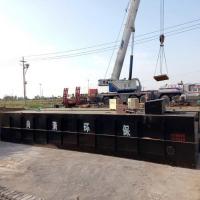
SQHG-50 Chemical Wastewater Treatment Equipment Carbon Steel 50T/D
The treatment of wastewater in chemical industrial parks is becoming increasingly important for water pollution control. Taking the the Taihu Lake Lake Basin in Jiangsu Province as an example, there are 5000 chemical enterprises in the basin, which discharge about 140 million m3 of chemical wastewater every year. The wastewater discharged by enterprises in chemical industrial parks has complex water quality, characterized by large changes in water quality, difficulty in degradation, toxicity, high salinity, and poor biodegradability. It is a typical toxic, harmful, and difficult to degrade industrial wastewater.

At present, there are various methods for treating wastewater in chemical industrial parks, such as zero valent iron, membrane bioreactor, air flotation, and micro electrolysis processes. These individual processes have high operating costs, unstable treatment effects, and are prone to secondary pollution. Hu Daqiang et al. adopted a pilot process route with pre-treatment A2/O-coagulation sedimentation as the main body, and the operating results showed that when the average COD of the influent was 1000mg/L and TKN124mg/L, the effluent COD was 80mg/L and NH3-N15mg/L, meeting the design requirements. Li Dongsheng et al. used physicochemical (iron carbon micro electrolysis, catalytic oxidation) pretreatment to treat high concentration wastewater, and then used hydrolysis acidification A/O process to treat mixed wastewater. The results showed that the COD of the treated effluent was less than 500mg/L, and the ammonia nitrogen was less than 35mg/L. The effluent quality met the requirements of the takeover. The COD removal rate of the pretreatment process reached 64%, and the nitrobenzene removal rate reached 94%. Ji Zhen et al. used a physicochemical pre-treatment-UASB hydrolysis acidification biological contact oxidation activated carbon biological filter process to treat a company's chemical wastewater. The results showed that the pre-treatment process can significantly reduce the COD and salt content of high concentration wastewater, and the overall treated effluent quality meets the takeover requirements.

The wastewater treatment process in the chemical park needs further
optimization. On the one hand, strict implementation of emission
standards puts forward clear requirements for wastewater treatment
in chemical industrial parks; On the other hand, due to the complex
raw materials used in the chemical production process and the
continuous improvement of production processes, the concentration
and composition of chemical wastewater are becoming increasingly
complex. This article takes wastewater from a chemical industry
park in Jiangsu as the research object, explores the treatment
effect of the system through the design of integrated processes,
and provides reference experience for similar wastewater treatment.
process flow
The process flow is shown in Figure 1.

Main structures and equipment
(1) Regulating pool. 3 underground reinforced concrete structures.
The total volume is 9500m3. Collect high concentration wastewater,
low concentration wastewater, and easily biodegradable wastewater
separately. 3 pipeline pumps, model IHF80-65-125; 2 submersible
sewage pumps, model WQ2210-413, N=5.5kW. 3 pipeline pumps, models
IHF125-80-160. Three ultrasonic level gauges.
(2) Coagulation sedimentation tank. Two, semi underground
reinforced concrete structures. Boundary dimension 13.25m × 3.5m ×
4.7m, surface load 0.65m3/(m2 • h). Two peripheral drive mud
scrapers, one PAM, PAC, and one calcium chloride dosing system
each.
(3) Anaerobic hydrolysis tank. 1 building, 2 groups, semi
underground, reinforced concrete structure. Boundary dimension
67.5m × 40.6m × 6.2m, HRT about 36h, 8 thrusters.
(4) Secondary sedimentation tank. 2, semi underground, reinforced
concrete structure. Adopting a radial sedimentation tank with
central inlet and peripheral outlet. Overall dimensions φ 28m × 6m.
2 peripheral drive sludge scrapers and 4 sludge reflux pumps, model
WL2260-450.
(5) Anoxic tank/aerobic tank. 1 building, 2 groups, semi
underground, reinforced concrete structure. Boundary dimension:
36.9m × 18.9m × 6.2m. The total residence time is 33.4 hours, with
an anaerobic residence time of about 8.8 hours and an aerobic
residence time of about 24.6 hours; 8 pushers, 3 mixed liquid
reflux pumps, and 1 set of microporous aerator. 3 blowers,
Q=28m3/min, P=45kW; Two blowers, one for use and one for backup,
Q=12.7m3/min, P=18.5kW.
(6) Three sedimentation tanks. 2, semi underground, reinforced
concrete structure. Overall dimensions φ 28m × 5.92m. The surface
hydraulic load is 0.35m3/(m2 • d). 2 central transmission mud
scrapers; 4 sludge reflux pumps.
(7) Quick filter. 1 building, semi underground, reinforced concrete
structure. Single seat overall size 10.9m × 10.9m × 4m, filtration
rate of 5m/h.
(8) Physicochemical sludge tank. 1 building, semi underground,
reinforced concrete structure. Overall dimensions φ 8.0m × 4.3m.
Two sludge pumps, N=5.5kW.
(9) Biochemical sludge tank. 1 building, semi underground,
reinforced concrete structure. External dimension 5m × 5m × 4.5m.
Two sludge pumps.
(10) Dehydration machine room. 1 room, above ground, frame
structure. Boundary dimension 22m × 12m × 4.5m. 2 filter presses; 1
set of PAM dosing device; 1 set of conveyor.


