Active Member
|
[China]

Address: Building B, Area A, Democracy Jiujiu Industrial City, Xihuan Road, Shajing Street, Baoan District, Shenzhen, China
Contact name:Frank

Shenzhen Rong Teng Hui Technology Co., Ltd |
|
|
SMT POGO PIN
1, the product performance: pogopin product contact parts material USES environmental brass + PA46, environmental protection of gold plating, can better waterproof, moistureproof, conductive performance is better; Spring of imported stainless steel fine wire, good elasticity, more durable, stretch can reach more than 10000 times;
2, the areas of application: the products are widely used in mobile communication products, electronic digital products, electronic medical equipment, game consoles, digital cameras, etc., mainly used in conductive or signal transmission, many current product adopts pogopin instead of metal shrapnel, more reliable performance, convenient production and delivery of more efficient;
3. Packing: pogopin products can braid (belt) packaging, needles, fitted with a plastic cap to automatic SMT processing, can be in bulk, convenient manual welding or reflow soldering machine, as well as to in the process of product transportation, better protection products;
4, environmental information: our company can provide the latest version of the SGS test report and material certificate.
Brief Introduction of SMT POGO Pin :
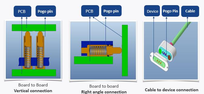
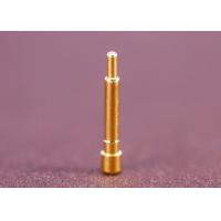
Pogo Pin is spring loaded probe which is made by precision instruments with riveting workmanship. It usually consists of plunger, tube and spring. Pogo pin is generally applied in the precision connection inside the electronics products such as mobile phones, communication devices, automotive, medical devices, aerospace devices and so on. Since pogo pin is very fine probe, it can make the finished connector light in weight, small in size and exquisite in look when it’s applied in a precision connector.
Features of SMT POGO PIN:
- Ball strucutre to protect spring from high current.
- Thru-hole tail for secure soldering.
- Solder-cup tail for wire attachment. (Recommended AWG19 or
greater)
- Available 2A per pin
- Working Height: 2.5mm ~ 8.3mm
- Spring Force: 0.9N or 1.08N
- Tube Bottom Diameter: 1.8mm ~ 2.5mm
Structural Features of SMT POGO PIN
With ball structure: The ball inside allows more buffer, so result in a even more reliable connection.
Bias structure: The biased tail of the plunger creates a lateral force, so further improves the contact.
Back drill structure: The back drilled plunger increases the space for the spring, so allows a shorter pogo pin for tight space.
Pogo pin Materials
| Parts | Materials | Surface treatment | Hazardous substances | Remarks |
| Plunger | C3604 | Ni1.4u~3.75u Au 0.4u | Lead is less than 4%, RoHS compliants | Forming Process C3604 for Lathe Tuming Maching |
| Tube | C3604 | Ni 1.4i~3.5u Au 0.1u | Lead is less than 4%, RoHS compliants | |
| Spring | SUS304 | N/A | ||
| Housing | PA46 LCP HPPA | N/A | Halogen free material | fire-protection rating UL94V-0 |
| Cap | PA46 HPPA | N/A | Halogen free material | fire-protection rating UL94V-0 |
Comparison of different structure of SMT POGO Pin
| Structure | Contact Impedance | Space saving | Amperage carrying | Reliability |
| A, With ball structure | ★★★★★ | ★★★☆☆ | ★★★★★ | ★★★★★ |
| B, Bias structure | ★★★★★ | ★★★★★ | ★★★★★ | ★★★★☆ |
| C, Back drill structure | ★★☆☆☆ | ★★★★★ | ★★☆☆☆ | ★★☆☆☆ |
Basic Specifications of SMT POGO Pin:
| ITEM | PERFORMANCE | NOTE |
| Rated voltage | Less than 36 Volte Dc | |
| Rated current | 2.0 Amperes | continuous per pin |
| Working temperature | -40 °C to 85 °C | |
| Storage temperature | -40 °C to 85 °C | |
| Woring environment humidity | 10% R.H. to 90% R.H. | |
| Durability | static testing 500,000 cycles, dynamic testing 10,000 cycles | life cycle |
| Contact impedance | 30m ohm Max. | the contac impeance should be lower than 30m ohm during the whole working stroke,so it's dynamic contact impedance, not contact impedance in a certain point |
| PIN interval impedance | 500M ohm Min. | pogo pin connector |
| ITEM | Performance | Note |
| Rated Current | 2A | - |
| Rated Voltage | AC/DC 12V | - |
| Contact Resistance | 50mΩmax (stillness) (At factory shipment) | 100mΩ after 100 times operation (After Durability test at Yokowo Regulation) |
| Insulation Resistance | 100MΩ (Min) | DC500V |
| Withstand Voltage | AC500V 1Min | Leak Current 3mA |
| Ambient Temp. | -40℃~+85℃ | - |
| Pin Force | 9.8N on a Pin from any direction | - |
| Pin Holding Strength | 4.9N on a Pin from axis direction | - |
| Cycle Durability | 20,000 times | Working Height |
| Temp./Humidity Cycle Test | Fig. 1 | JIS C60068-2-38 |
| Mechanical Shock Durability | 490m/s² | JIS C60068-2-27 |
| Soldering Temp. | 350℃ 3sec | Soldering Iron |
| Reflow Temp. | Fig.2 | - |
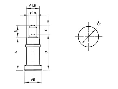
Basic Dimensions of SMT POGO Pin:
| ∅ A | B | C | D | E | FORCE(GF) | PART NUMBER |
| 1.20 | 0.60 | 1.45 | 1.95 | 1.60 | 35gf Min | 20101011233 |
| 2.00 | 0.40 | 2.20 | 3.00 | 2.40 | 90 Min | 101245-1 |
| 1.80 | 0.50 | 2.30 | 3.00 | 2.50 | 90 Min | 10101011363 |
| 1.65 | 0.40 | 2.20 | 3.00 | 2.50 | 90 Min | 101089-1 |
| 1.65 | 0.40 | 2.20 | 3.00 | 2.50 | 90 Min | 101603-1 |
| 1.65 | 0.60 | 2.40 | 3.20 | 2.70 | 90 Min | 101022-1 |
| 1.80 | 0.40 | 2.50 | 3.30 | 2.80 | 90±20 | 101080-1 |
| 2.00 | 0.40 | 2.50 | 3.30 | 2.80 | 90±20 | 101121-1 |
| 2.00 | 0.40 | 2.50 | 3.50 | 2.80 | 100±35 | 101281-1 |
| 2.00 | 0.40 | 2.50 | 3.50 | 2.90 | 100±30 | 101009-1 |
SMT POGO Pin
| Type | Working Height | Spring Force | Rated Current | A | B | C | D | E | F |
| 2307 | 2.5 | 0.9N | 2A | 2.3 | 0.7 | 2.5 | 0.5 | 1.8 | 2.4 |
| 2509 | 2.8 | 0.9N | 2A | 2.5 | 0.9 | 2.8 | 0.6 | 1.8 | 2.4 |
| 2809 | 3.1 | 1.08N | 2A | 2.8 | 0.9 | 3.1 | 0.6 | 1.8 | 2.4 |
| 2910 | 3.2 | 1.08N | 2A | 2.9 | 1.0 | 3.2 | 0.7 | 1.8 | 2.4 |
| 3111 | 3.4 | 1.08N | 2A | 3.1 | 1.1 | 3.4 | 0.8 | 1.8 | 2.4 |
| 3212 | 3.5 | 1.08N | 2A | 3.2 | 1.2 | 3.5 | 0.9 | 1.8 | 2.4 |
| 3413 | 3.8 | 1.08N | 2A | 3.4 | 1.3 | 3.8 | 0.9 | 2.0 | 2.6 |
| 3614 | 4.0 | 1.08N | 2A | 3.6 | 1.4 | 4.0 | 1.0 | 2.0 | 2.6 |
| 3915 | 4.4 | 1.08N | 2A | 3.9 | 1.5 | 4.4 | 1.0 | 2.0 | 2.6 |
| 4215 | 4.7 | 1.08N | 2A | 4.2 | 1.5 | 4.7 | 1.0 | 2.5 | 3.1 |
| 4617 | 5.2 | 1.08N | 2A | 4.6 | 1.7 | 5.2 | 1.1 | 2.5 | 3.1 |
| 5117 | 5.7 | 1.08N | 2A | 5.1 | 1.7 | 5.7 | 1.1 | 2.5 | 3.1 |
| 5517 | 6.1 | 1.08N | 2A | 5.5 | 1.7 | 6.1 | 1.1 | 2.5 | 3.1 |
| 5920 | 6.6 | 1.08N | 2A | 5.9 | 2.0 | 6.6 | 1.3 | 2.5 | 3.1 |
| 6220 | 6.9 | 1.08N | 2A | 6.2 | 2.0 | 6.9 | 1.3 | 2.5 | 3.1 |
| 6520 | 7.2 | 1.08N | 2A | 6.5 | 2.0 | 7.2 | 1.3 | 2.5 | 3.1 |
| 7025 | 7.8 | 1.08N | 2A | 7.0 | 2.5 | 7.8 | 1.7 | 2.5 | 3.1 |
| 7525 | 8.3 | 1.08N | 2A | 7.5 | 2.5 | 8.3 | 1.7 | 2.5 | 3.1 |