Active Member
|
[China]

Address: Building B, Area A, Democracy Jiujiu Industrial City, Xihuan Road, Shajing Street, Baoan District, Shenzhen, China
Contact name:Frank

Shenzhen Rong Teng Hui Technology Co., Ltd |

|
|
SMT POGO PIN
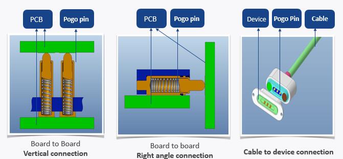
A basic spring-loaded pin consists of 3 main parts: a plunger, barrel, and spring. When force is applied to the pin, the spring is compressed and the plunger moves inside the barrel. The shape of the barrel retains the plunger, stopping the spring from pushing it out when the pin is not locked in place.
In the design of electrical contacts, a certain amount of friction is required to hold a connector in place and retain the contact finish. However, high friction is undesirable because it increases stress and wear on the contact springs and housings. Thus, a precise normal force, typically around 1 newton, is required to generate this friction. Since a spring-loaded pin needs to have a slight gap between the plunger and barrel so that it can slide easily, momentary disconnections can happen when there is vibration or movement. In order to counter this, the plunger usually has a small tilt to ensure a continuous connection.
Pogo pin Materials
| Parts | Materials | Surface treatment | Hazardous substances | Remarks |
| Plunger | C3604 | Ni1.4u~3.75u Au 0.4u | Lead is less than 4%, RoHS compliants | Forming Process C3604 for Lathe Tuming Maching |
| Tube | C3604 | Ni 1.4i~3.5u Au 0.1u | Lead is less than 4%, RoHS compliants | |
| Spring | SUS304 | N/A | ||
| Housing | PA46 LCP HPPA | N/A | Halogen free material | fire-protection rating UL94V-0 |
| Cap | PA46 HPPA | N/A | Halogen free material | fire-protection rating UL94V-0 |
Features of SMT POGO PIN:
- Ball strucutre to protect spring from high current.
- Thru-hole tail for secure soldering.
- Solder-cup tail for wire attachment. (Recommended AWG19 or
greater)
- Available 2A per pin
- Working Height: 2.5mm ~ 8.3mm
- Spring Force: 0.9N or 1.08N
- Tube Bottom Diameter: 1.8mm ~ 2.5mm
Structural Features of SMT POGO PIN
With ball structure: The ball inside allows more buffer, so result in a even more reliable connection.
Bias structure: The biased tail of the plunger creates a lateral force, so further improves the contact.
Back drill structure: The back drilled plunger increases the space for the spring, so allows a shorter pogo pin for tight space.
Comparison of different structure of SMT POGO Pin
| Structure | Contact Impedance | Space saving | Amperage carrying | Reliability |
| A, With ball structure | ★★★★★ | ★★★☆☆ | ★★★★★ | ★★★★★ |
| B, Bias structure | ★★★★★ | ★★★★★ | ★★★★★ | ★★★★☆ |
| C, Back drill structure | ★★☆☆☆ | ★★★★★ | ★★☆☆☆ | ★★☆☆☆ |
Basic Specifications of SMT POGO Pin:
| ITEM | PERFORMANCE | NOTE |
| Rated voltage | Less than 36 Volte Dc | |
| Rated current | 2.0 Amperes | continuous per pin |
| Working temperature | -40 °C to 85 °C | |
| Storage temperature | -40 °C to 85 °C | |
| Woring environment humidity | 10% R.H. to 90% R.H. | |
| Durability | static testing 500,000 cycles, dynamic testing 10,000 cycles | life cycle |
| Contact impedance | 30m ohm Max. | the contac impeance should be lower than 30m ohm during the whole working stroke,so it's dynamic contact impedance, not contact impedance in a certain point |
| PIN interval impedance | 500M ohm Min. | pogo pin connector |
| ITEM | Performance | Note |
| Rated Current | 2A | - |
| Rated Voltage | AC/DC 12V | - |
| Contact Resistance | 50mΩmax (stillness) (At factory shipment) | 100mΩ after 100 times operation (After Durability test at Yokowo Regulation) |
| Insulation Resistance | 100MΩ (Min) | DC500V |
| Withstand Voltage | AC500V 1Min | Leak Current 3mA |
| Ambient Temp. | -40℃~+85℃ | - |
| Pin Force | 9.8N on a Pin from any direction | - |
| Pin Holding Strength | 4.9N on a Pin from axis direction | - |
| Cycle Durability | 20,000 times | Working Height |
| Temp./Humidity Cycle Test | Fig. 1 | JIS C60068-2-38 |
| Mechanical Shock Durability | 490m/s² | JIS C60068-2-27 |
| Soldering Temp. | 350℃ 3sec | Soldering Iron |
| Reflow Temp. | Fig.2 | - |
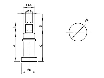
Basic Dimensions of SMT POGO Pin:
| ∅ A | B | C | D | E | FORCE(GF) | PART NUMBER |
| 1.20 | 0.60 | 1.45 | 1.95 | 1.60 | 35gf Min | 20101011233 |
| 2.00 | 0.40 | 2.20 | 3.00 | 2.40 | 90 Min | 101245-1 |
| 1.80 | 0.50 | 2.30 | 3.00 | 2.50 | 90 Min | 10101011363 |
| 1.65 | 0.40 | 2.20 | 3.00 | 2.50 | 90 Min | 101089-1 |
| 1.65 | 0.40 | 2.20 | 3.00 | 2.50 | 90 Min | 101603-1 |
| 1.65 | 0.60 | 2.40 | 3.20 | 2.70 | 90 Min | 101022-1 |
| 1.80 | 0.40 | 2.50 | 3.30 | 2.80 | 90±20 | 101080-1 |
| 2.00 | 0.40 | 2.50 | 3.30 | 2.80 | 90±20 | 101121-1 |
| 2.00 | 0.40 | 2.50 | 3.50 | 2.80 | 100±35 | 101281-1 |
| 2.00 | 0.40 | 2.50 | 3.50 | 2.90 | 100±30 | 101009-1 |
SMT POGO Pin
| Type | Working Height | Spring Force | Rated Current | A | B | C | D | E | F |
| 2307 | 2.5 | 0.9N | 2A | 2.3 | 0.7 | 2.5 | 0.5 | 1.8 | 2.4 |
| 2509 | 2.8 | 0.9N | 2A | 2.5 | 0.9 | 2.8 | 0.6 | 1.8 | 2.4 |
| 2809 | 3.1 | 1.08N | 2A | 2.8 | 0.9 | 3.1 | 0.6 | 1.8 | 2.4 |
| 2910 | 3.2 | 1.08N | 2A | 2.9 | 1.0 | 3.2 | 0.7 | 1.8 | 2.4 |
| 3111 | 3.4 | 1.08N | 2A | 3.1 | 1.1 | 3.4 | 0.8 | 1.8 | 2.4 |
| 3212 | 3.5 | 1.08N | 2A | 3.2 | 1.2 | 3.5 | 0.9 | 1.8 | 2.4 |
| 3413 | 3.8 | 1.08N | 2A | 3.4 | 1.3 | 3.8 | 0.9 | 2.0 | 2.6 |
| 3614 | 4.0 | 1.08N | 2A | 3.6 | 1.4 | 4.0 | 1.0 | 2.0 | 2.6 |
| 3915 | 4.4 | 1.08N | 2A | 3.9 | 1.5 | 4.4 | 1.0 | 2.0 | 2.6 |
| 4215 | 4.7 | 1.08N | 2A | 4.2 | 1.5 | 4.7 | 1.0 | 2.5 | 3.1 |
| 4617 | 5.2 | 1.08N | 2A | 4.6 | 1.7 | 5.2 | 1.1 | 2.5 | 3.1 |
| 5117 | 5.7 | 1.08N | 2A | 5.1 | 1.7 | 5.7 | 1.1 | 2.5 | 3.1 |
| 5517 | 6.1 | 1.08N | 2A | 5.5 | 1.7 | 6.1 | 1.1 | 2.5 | 3.1 |
| 5920 | 6.6 | 1.08N | 2A | 5.9 | 2.0 | 6.6 | 1.3 | 2.5 | 3.1 |
| 6220 | 6.9 | 1.08N | 2A | 6.2 | 2.0 | 6.9 | 1.3 | 2.5 | 3.1 |
| 6520 | 7.2 | 1.08N | 2A | 6.5 | 2.0 | 7.2 | 1.3 | 2.5 | 3.1 |
| 7025 | 7.8 | 1.08N | 2A | 7.0 | 2.5 | 7.8 | 1.7 | 2.5 | 3.1 |
| 7525 | 8.3 | 1.08N | 2A | 7.5 | 2.5 | 8.3 | 1.7 | 2.5 | 3.1 |