

Active Member
|
[China]

Address: Floor 4, Unit C, Building 2, Skyworth Innovation Valley, Shiyan Street, Baoan District, Shenzhen, Guangdong Province, China
Contact name:Yang

Zhejiang Risesun Science and Technology Co.,Ltd. |
|
|
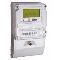
Single Phase Smart active Energy Meter with Built-in Module
General introduction
Single Phase Smart active Energy Meter with Built-in Module can measure the import and the export active energy. It is with TOU and step tariff function, and can be with PLC or RF module. It can be controlled to disconnect and reconnect the load remotely.
Main functions
1. Display and indication: Large screen LCD, abundant graphics and
hinting text. The displayed contents can scroll automatically or be
trigged by button, and the displayed items can be configured as per
the requirements. It has backlight. Meter can be read during power
outage.
2. Metering and measurements: It can measure the import and the
export active energy and the total active energy. The total active
energy can be configured by the import active energy and the export
active energy as per the requirements. It can measure voltage,
current, power, power factor, neutral current (optional), etc.
3. TOU:4 tariffs; Built-in 2 sets of time zone tables and 2 sets of
daily period tables, which can be configured as per the
requirements.Moreover, the switching time for both 2 sets of time
zone tables and 2 sets of day profile table can be set and smoothly
switch. It can be set 14day profile and 254 holidays(special day).
4. Data snapshot: It supports various ways of freezing, which include daily freezing, hourly freezing, occasional freezing, immediate freezing.
5. Event logs: It can separately record latest 10 times events,
such as power outage, programming, time correction, meter cover
open,disconnection and reconnection, reset of events, reset of
meter, etc.
6. Communication interface: The meter has one far infrared
interface, one RS485 and one PLC/RF(PLC and RF can be
interchangeable.)module interface. Interfaces are independent.
Communication protocol of meter conforms to DL/T645-2007.
Technical specifications
| Items | contents |
| Techniacl Standards | IEC62052-11; IEC62053-21 |
| Protocol | DL/T 645-2007 |
| Accuracy | Active: Class 1 |
| Reference voltage | 120V/220V/230V/240V |
| Current | CT connection:1.5(6)A. Direct connection:10(40)A,10(60)A,20(80)A,10(100)A |
| Reference frequency | 50 / 60Hz |
| Power consumption | <1.5W,6VA |
| Operation voltage range | 0.8Un~1.2Un |
| Limited operation voltage range | 0.7Un~1.3Un |
| Operation temperature | -25℃~ +60℃ |
| Limited operation temperature range | -40℃~ +70℃ |
| RTC deviation | ≤0.5s/d |
| Life time | 15 years |
| Size | 160mm(L)×112mm(W)×71mm(H) |
| Net weight | About 0.6kg |
AMI System Architecture Diagram

AMI System General
Advanced Metering Infrastructure (AMI) is the technology of
automatically collecting data from energy metering devices and
transferring that data to a central database by communication
technology for remote control and analyzing. RS801E AMI system is
composed of management software, remote communication channel,
power management terminal, regional summary meter, local
communication channel, user energy meter and other equipments.
Power companies can build AMI system to replace the manual meter
reading to save human resources, reduce meter reading costs and
improve meter reading efficiency and success rate. The AMI system
reduces the error rate, the electricity loss and eliminates the
false meter reading by personnel. The AMI system also can monitor
the status of the users and find the abnormal information to alarm
in time. It also collects data from regional summary meter and the
regional line loss can be calculated. The software system is
developed by Java and it can be deployed on Windows, Unix, and
other major operating systems. The system is developed based on
Enterprise-class Jave EE standards, a three-tier technical
architecture (client / middleware server / database server) as the
basis for the system. The system has excellent openness,
scalability, flexibility and high reliability. Many advanced
computer and communication technologies are used on this AMI system
to satisfy the needs of power companies in different


