

Active Member
|
[China]

Address: Huidu Headquarters Industrial Park, No. 4 Xinye Road, High-tech West District, Chengdu City, Sichuan Province, CN
Contact name:Scott zhao

Chengdu SinoScite Technology Co., Ltd. |
|
|
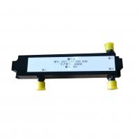
RF Components Microwave RF Directional Coupler Used Within A Meter Detecting The Standing Wave Ratio
Quick Details
| 1 | Product Type | Coupler |
| 2 | Model | CP17.7-23.55GS-3149 |
| 3 | Working Frequency | 17.7-23.55GHz |
| 4 | Insertion Loss | ≤1.4dB |
| 5 | In-Band Fluctuation | ≤0.5dB |
| 6 | Coupling | 10±1.5dB |
| 7 | Coupling Consistency | ≤±0.75dB |
| 8 | Directionality | ≥15dB |
| 9 | Input And Output VSWR | ≤1.4 |
| 10 | Coupled Port VSWR | ≤1.5 |
| 11 | Input And Output Interface | Coaxial (2.92-K) |
| 12 | Coupling Port Output | Coaxial (2.92-K) |
| 13 | Material | Brass silver plated |
| 14 | Surface Treatment | Black paint |


