Active Member
|
[China]

Address: Room1301, Building 11, yard 88 , Sanluju Road, Fengtai District, Beijing, China
Contact name:

Beijing Tianyihongda Science & Technology Development Co., LTD |
|
|
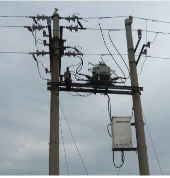
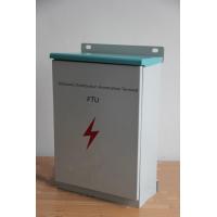
power distribution automation feeder terminal unit controlling and detecting fault and transmitting measured data from c
This is a new HV switch control device equipped with both the
imported DSP high-speed sampling chips and the high-performance ARM
chips, and can fast and stably finish the monitoring on the switch.
It boasts of such functions as the protection, measuring,
controlling, monitoring, communication, remote control and so on
and features high integration level, flexible configuration and
user-friendly interface, widely applied to the radiant and ring
network power supply systems to help the systems identify transient
and permanent line faults, eliminate the impact of transient line
faults automatically, isolate the permanent fault segments to avoid
prolonged power failure in large area, and automatically recover
the power supply in fault-free areas, so as to realize the
automation of power distribution network in a economical and
practical way.
Atmospheric pressure: 66kPa~108kPa.
Operating environment: no explosive and flammable materials, no air
or conductive dust which will damage the insulation and cause metal
corrosion, no serious mold and no severe vibration sources, with
measures to defend against rain, snow, wind, sand, dust and static
electricity.The product is equipped with RS-232/485 (standard
configuration: RS-232) communication interface to fulfill the wired
remote control, wireless remote control, optical fiber remote
control, carrier remote control and other kinds of remote control
by the support of related equipment. Remote signaling, remote
metering, remote control and remote regulating can be carried out
through local communication ports. Communication modes: GSM
SMS, PDA wireless communication, GPRS wireless network, optical
fiber communication, Ethernet, carrier communication through power
broadband, etc.
Communication protocols: Various protocols are supported and
can be adjusted as required. The basic configuration supports 101
balanced protocol, 101 unbalanced protocol, 104 protocol, DNP3.0
and Modbus communication protocol (standard configuration: 101
balanced protocol).
The remote controller of this device adopts the coding mode of 1 to
1 (i.e. the code of transmitter and that of receiver are the same,
which are set as a unique code before leaving the factory). The
opening and closing can be operated only after unlocking. After
finishing the operation, the device will enter into the safe mode
with multiple protections including locked remote operation, so as
to avoid misoperation or false operation. The effective distance of
remote controller is not more than 30 meters. The detailed
operation of the remote controller is as follows:
If the device is opened, the steps for closing the device are:
press the “Unlock” button on the remote controller to unlock the
device and then press the “Close” button on the remote controller
to close the device.
If the device is close, the steps for opening the device are: press
the “Unlock” button on the remote controller to unlock the device
and then press the “Open” button on the remote controller to open
the device.
| Total load capacity within the user’s boundary (KVA) | <1250 | 1250-2500 | 2500-4000 | 4000-5600 | >5600 |
| Fixed value (A) | 120 | 240 | 360 | 480 | 600 |
For the system in which the neutral point is earthed by low
resistance, it is recommended to choose 600A as the fixed value for
phase-to-phase protection to prevent starting the phase-to-phase
protection when there is an earthing fault. Fixed value for quick
break is generally 3-7 times of over-current fixed value, which is
subject to the actual line.
Note: This part is about the fixed values of over-current
protection and earthing protection. Please skip this part if there
is no fixed value for protection, e.g. pure voltage protection
method.
Table for Selection of Fixed Values for Zero-sequence Protection Current
| Length of cable at switch load side (m) | 50 | 100 | 150 | 200 | 250 | 300 | 350 | 400 | 450 | |
| Length of overhead line at switch load side (m) | <1000 | <4000 | ||||||||
| Fixed value (A) | 0.2 | 0.4 | 0.6 | 0.8 | 1.0 | 1.2 | 1.4 | 1.6 | 1.8 | 2.0 |
| Length of cable at switch load side (m) | 480 | 500 | 550 | 600 | 650 | 700 | 750 | 800 | 850 | 900 |
| Fixed value (A) | 2.2 | 2.4 | 2.6 | 2.8 | 3.0 | 3.2 | 3.4 | 3.6 | 3.8 | 4.0 |
Calculation formula for fixed values: Fixed value of current =1.5×3×(S1×L1+S2×L2)
L1 is the total length of overhead line at boundary switch load side. S1 is the empirical value of capacitive current of overhead line per km per phase. The recommended value is 0.02A/km.
L2 is the total length of cable at boundary switch load side. S2 is the empirical value of capacitive current of cable per km per phase. The recommended value is 1A/km.
Selection of Fixed Values for Zero-sequence Protection Delay
Choose 1S when the neutral point is not earthed or earthed by arc suppression coil. Choose OS or lower when the neutral point is earthed by low resistance.
The calculation of fixed values for zero-sequence protection current only depends on the direct earth capacitance of cable or overhead line at switch load side. The table above is the results of approximate amount multiplied by safety factor. Users can calculate personally according to the actual condition of the line at switch load side. If there are both cable and overhead line at switch load side, add their direct earth capacitances together. The safety factor shall be chosen between 1.5~3 (It is recommended that a larger safety factor shall be chosen when the fixed value is relatively small, while a smaller one shall be chosen when the fixed value is relatively large.)
Table for Selection of Fixed Values for Phase-to-Phase Protection Current
| Total load capacity within the user’s boundary (KVA) | <1250 | 1250-2500 | 2500-4000 | 4000-5600 | >5600 |
| Fixed value (A) | 120 | 240 | 360 | 480 | 600 |
For the system in which the neutral point is earthed by low resistance, it is recommended to choose 600A as the fixed value for phase-to-phase protection to prevent starting the phase-to-phase protection when there is an earthing fault. Fixed value for quick break is generally 3-7 times of over-current fixed value, which is subject to the actual line.
Note: This part is about the fixed values of over-current protection and earthing protection. Please skip this part if there is no fixed value for protection, e.g. pure voltage protection method.