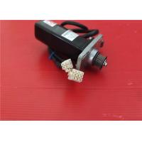
YASKAWA Industrial 3000r/min 0.91A SGMAH Japan Sigma II 100W
SGMAH-01A1A-HL11
Specifications
Manufacturer: Yaskawa
Product number: SGMAH-01A1A-HL11
Description: SGMAH-01A1A-HL11 is an Motors-AC Servo manufactured by
Yaskawa
Servomotor Type: SGMAH Sigma II
Rated Output: 50W (0.07HP)
Power Supply: 200V
Encoder Specifications: 13-bit (2048 x 4) Incremental Encoder;
Standard
Revision Level: Standard
Shaft Specifications: Straight shaft without keyway
Accessories: Standard; without brake
Option: None
Type: none
OTHER SUPERIOR PRODUCTS
Yasakawa Motor, Driver SG- Mitsubishi Motor HC-,HA-
Westinghouse Modules 1C-,5X- Emerson VE-,KJ-
Honeywell TC-,TK- Fanuc motor A0-
Rosemount transmitter 3051- Yokogawa transmitter EJA-
Contact person: Anna
E-mail: wisdomlongkeji@163.com
Cellphone: +0086-13534205279
Similar Products
SGMAH-A5A1A21
SGMAH-A5A1A2C
SGMAH-A5A1A2E
SGMAH-A5A1A41D
SGMAH-A5A1A4C
SGMAH-A5A1A-YR11
SGMAH-A5A1A-YR31
SGMAH-A5A1F21
SGMAH-A5A1F2C
SGMAH-A5A1F2CD
SGMAH-A5A1F41
SGMAH-A5A4F41
SGMAH-A5AAA21
SGMAH-A5AAA2B
SGMAH-A5AAA61D
SGMAH-A5AAA61D-OY
SGMAH-A5AAAG161
SGMAH-A5AAAG761
SGMAH-A5AAAG761D
SGMAH-A5AAAH161
The AC induction motor is well suited to applications requiring
constant speed operation. In general, the induction motor is
cheaper and easier to maintain compared to other alternatives.
The induction motor is made up of the stator, or stationary
windings, and the rotor. The stator consists of a series of wire
windings of very low resistance permanently attached to the motor
frame. As a voltage and a current is applied to the stator winding
terminals, a magnetic field is developed in the windings. By the
way the stator windings are arranged, the magnetic field appears to
synchronously rotate electrically around the
inside of the motor housing.
The rotor is comprised of a number of thin bars, usually aluminum,
mounted in a laminated cylinder. The bars are arranged horizontally
and almost parallel to the rotor shaft. At the ends of the rotor,
the bars are connected together with a “shorting ring.” The rotor
and stator are separated by an air gap which allows free rotation
of the rotor.
The magnetic field generated in the stator induces an EMF in the
rotor bars. In turn, a current is produced in the rotor bars and
shorting ring and another magnetic field is induced in the rotor
with an opposite polarity of that in the stator. The magnetic
field, revolving in the stator, will then produces the torque which
will “pull” on the field in the rotor and establish rotor rotation.
In addition to being classified by their step angle stepper motors
are also classified according to frame sizes
which correspond to the diameter of the body of the motor. For
instance a size 11 stepper motor has a body diameter of
approximately 1.1 inches. Likewise a size 23 stepper motor has a
body diameter of 2.3 inches (58 mm), etc. The body length may
however, vary from motor to motor within the same frame size
classification. As a general rule the available torque output from
a motor of a particular frame size will increase with increased
body length.
Power levels for IC-driven stepper motors typically range from
below a watt for very small motors up to 10 –
20 watts for larger motors. The maximum power dissipation level or
thermal limits of the motor are seldom
clearly stated in the motor manufacturers data. To determine this
we must apply the relationship P␣ =V ×␣ I.
For example, a size 23 step motor may be rated at 6V and 1A per
phase. Therefore, with two phases energized the motor has a rated
power dissipation of 12 watts. It is normal practice to rate a
stepper motor at the power dissipation level where the motor case
rises 65°C above the ambient in still air. Therefore, if the motor
can be mounted to a heatsink it is often possible to increase the
allowable power dissipation level. This is important as the motor
is designed to be and should be used at its maximum power
dissipation ,to be efficient from a size/output power/cost point of
view.