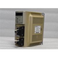
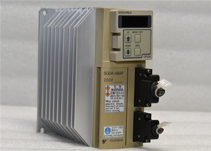
Industrial Yaskawa 200-230V Servo Drive SERVOPACK 750W CNC/ROUTER
SGDA-08AP
Quick Details
SGDA-08AP
• 750W (0.13HP) Rated Capacity
• 200-230 V AC Input
• 230 V Max Output
• Position Control (Digital Input)
Features
Compact Design
Easy Operation
Simple Wiring
Improved Environmental Resistance
Description
The Yaskawa SGDA Servopack features superior functions and
performance. Its compact design allows a volume ratio approximately
1/4 that of the conventional servo amplifier model. The SGDA
features an auto-tuning function, JOG operation, various monitoring
functions, and a PC monitoring function. It is also compatible with
incremental encoders or absolute encoder feedback. The servo
amplifier circuit board has been coated with varnish to improve
environmental resistance.
Similar Products
SGDA-02VP
SGDA-03BP
SGDA-03BP+SGMP-03B312
SGDA-03BPY122
SGDA-03SP
SGDA-04AH
SGDA-04AP
SGDA-04APP
SGDA-04AS
SGDA-04AS+SGM-04A3NT12
SGDA-04ASP
SGDA-04BS
SGDA-04VP
SGDA-04VP
SGDA-04VS
SGDA-05ADG+SGMG-05A2A
SGDA-08AP
SGDA-08APP
SGDA-08APPY128
SGDA-08AS
SGDA-08ASP
SGDA-08ASP SGDA-08AS
SGDA-08VP
SGD-A3AN
SGD-A5AN
SGD-A5BH
SGDA-A3AP
SGDA-A3BPM
SGDA-A3BS
SGDA-A3BS
SGDA-A3CPY14
SGDA-A3VP
SGDA-A3VS
SGDA-A5AP
SGDA-A5AS
SGDA-A5ASY109
SGDA-A5BP
SGDA-A5BS
SGDA-A5VP
SGDA-A5VPY197
When a current-carrying conductor is placed in a magnetic Weld, it
experiences a force. Experiment shows that the magnitude of the
force depends directly on the current in the wire, and the strength
of the magnetic Weld, and that the force is greatest when the
magnetic Weld is perpendicular to the
conductor.
In the set-up shown in Figure 1.1, the source of the magnetic Weld
is a bar magnet, which produces a magnetic Weld as shown in Figure
1.2.
The notion of a ‘magnetic Weld’ surrounding a magnet is an abstract
idea that helps us to come to grips with the mysterious phenomenon
o fNSNSNSNSFigure 1.2 Magnetic Xux lines produced by a permanent
magnet
Electric Motors 3
magnetism: it not only provides us with a convenient pictorial way
ofpicturing the directional eVects, but it also allows us to
quantify the ‘strength’ of the magnetism and hence permits us to
predict the various eVects produced by it
Nearly all motors exploit the force which is exerted on a
currentcarrying conductor placed in a magnetic Weld. The force can
be demonstrated by placing a bar magnet near a wire carrying
current (Figure 1.1), but anyone trying the experiment will
probably be disappointed to discover how feeble the force is, and
will doubtless be left wondering how such an unpromising eVect can
be used to make eVective motors.
We will see that in order to make the most of the mechanism, we
need to arrange a very strong magnetic Weld, and make it interact
with manyconductors, each carrying as much current as possible. We
will also see later that although the magnetic Weld (or
‘excitation’) is essential to the working of the motor, it acts
only as a catalyst, and all of the mechanical output power comes
from the electrical supply to the conductors on which the force is
developed. It will emerge later that in some motors the parts of
the machine responsible for the excitation and for the energy
converting functions are distinct and self-evident. In the d.c.
motor, for example, the excitation is provided either by permanent
magnets or by Weld coils wrapped around clearly deWned projecting
Weld poles on the stationary part, while the conductors on which
force is developed are on the rotor and supplied with current via
sliding brushes. In many motors,
however, there is no such clear-cut physical distinction between
the ‘excitation’ and the ‘energy-converting’ parts of the machine,
and a single stationary winding serves both purposes. Nevertheless,
we will
Wnd that identifying and separating the excitation and
energy-converting functions is always helpful in understanding how
motors of all types operate.
Returning to the matter of force on a single conductor, we will
Wrst look at what determines the magnitude and direction of the
force,NS Force
Current in conductor
Figure 1.1 Mechanical force produced on a current-carrying wire in
a magnetic Weld 2 Electric Motors and Drives before turning to ways
in which the mechanism is exploited to produce rotation. The
concept of the magnetic circuit will have to be explored, since
this is central to understanding why motors have the shapes they
do. A brief introduction to magnetic Weld, magnetic Xux, and Xux
density is included before that for those who are not familiar with
the ideas involved
How do you size a VFD drive for an application and feel confident
it's going to work? First, you must understand the requirements of
the load. It helps also if you understand the difference between
horsepower and torque. As electrical people, we tend to think of
loads in horsepower ratings instead of torque ratings. When was the
last time you sized something based on torque?
Thus, both torque and horsepower must be carefully examined.
Torque. Torque is an applied force that tends to produce rotation
and is measured in lb-ft or lb-in.
All loads have a torque requirement that must be met by the motor.
The purpose of the motor is
to develop enough torque to meet the requirements of the load.
Actually, torque can be thought of as "OOUMPH". The motor has to
develop enough "OOUMPH"
to get the load moving and keep it moving under all the conditions
that may apply.
Horsepower. Horsepower (hp) is the time rate at which work is being
done. One hp is the force
required to lift 33,000 lbs 1 ft in 1 min. If you want to get the
work done in less time, get yourself
more horses!
Here are some basic equations that will help you understand the
relationship between hp, torque,
and speed.
hp = (Torque x Speed)/5250 (eq. 1)
Torque = (hp x 5250)/Speed (eq. 2)
As an example, a 1-hp motor operating at 1800 rpm will develop 2.92
lb-ft of torque.
Know your load torque requirements Every load has distinct torque
requirements that vary with the load's operation; these torques
must be supplied by the motor via the VFD. You should have a clear
understanding of these torques.
* Break-away torque: torque required to start a load in motion
(typically greater than the torque required to maintain motion).
* Accelerating torque: torque required to bring the load to
operating speed within a given time.
* Running torque: torque required to keep the load moving at all
speeds.
* Peak torque: occasional peak torque required by the load, such as
a load being dropped on a conveyor.
* Holding torque: torque required by the motor when operating as a
brake, such as down hill loads and high inertia machines.
The dotted lines in Figure 1.2 are referred to as magnetic Xux
lines, or simply Xux lines. They indicate the direction along which
iron Wlings (or small steel pins) would align themselves when
placed in the Weld of the bar magnet. Steel pins have no initial
magnetic Weld of their own, so there is no reason why one end or
the other of the pins should point to a particular pole of the bar
magnet.
However, when we put a compass needle (which is itself a permanent
magnet) in the Weld we Wnd that it aligns itself as shown in Figure
1.2. In the upper half of the Wgure, the S end of the
diamond-shaped compass settles closest to the N pole of the magnet,
while in the lower half of the Wgure, the N end of the compass
seeks the S of the magnet. This immediately suggests that there is
a direction associated with the lines of Xux, as shown by the
arrows on the Xux lines, which conventionally are taken as
positively directed from the N to the S pole of the barmagnet.
OTHER SUPERIOR PRODUCTS
Yasakawa Motor, Driver SG- Mitsubishi Motor HC-,HA-
Westinghouse Modules 1C-,5X- Emerson VE-,KJ-
Honeywell TC-,TK- Fanuc motor A0-
Rosemount transmitter 3051- Yokogawa transmitter EJA-
Contact person: Anna
E-mail: wisdomlongkeji@163.com
Cellphone: +0086-13534205279