|
|
[China]

Trade Verify
Contact name:Sherlin

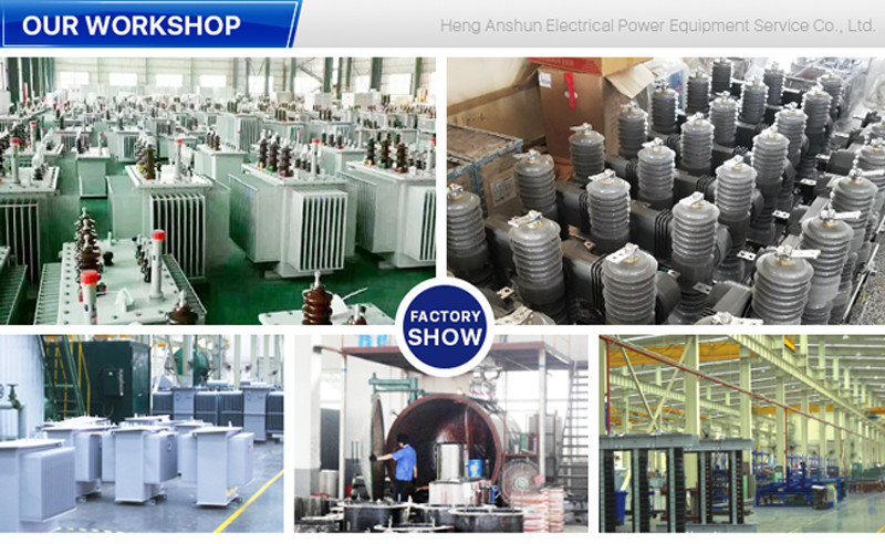
GuangDong Heng AnShun Electrical Power Equipment Service Co., Ltd. |
|
Verified Suppliers
|

|
|
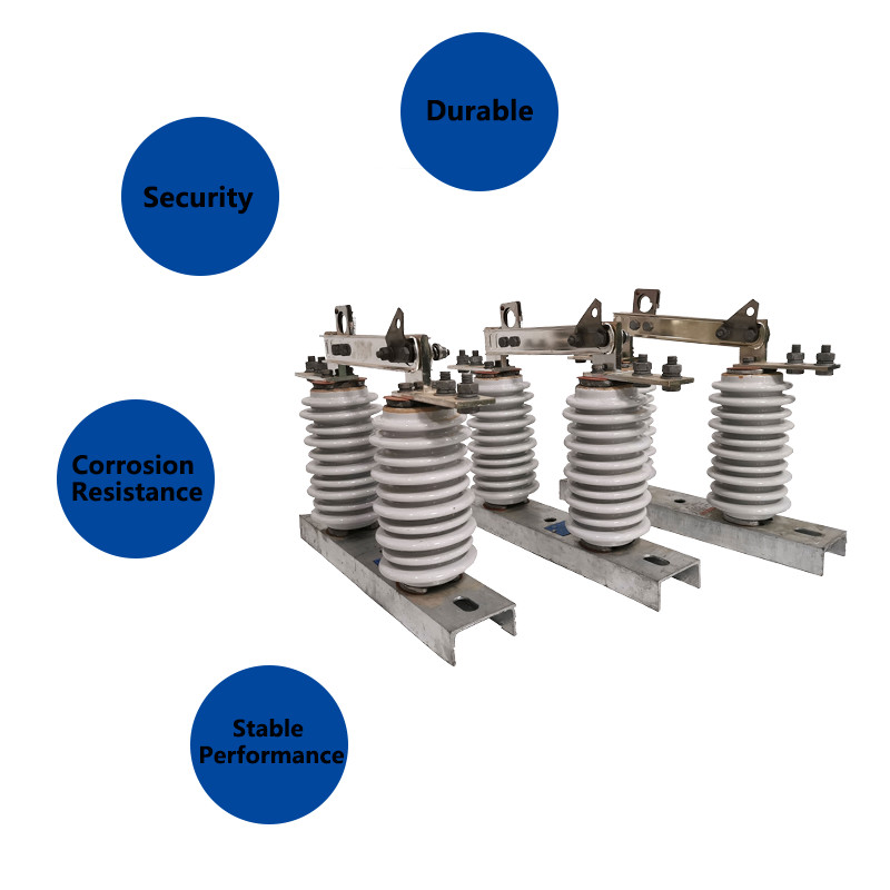
Outdoor High Voltage Electrical Isolator Distribution System
Insulation And Conduction Operated Hookstick
Product Description:
High voltage electrical isolators are commonly used in power
transmission and distribution systems, where they provide a means
of supporting and isolating high voltage power lines and equipment.
They are designed to withstand high levels of voltage and
electrical current, and are typically used in applications where
reliability and safety are critical.
The construction of high voltage electrical isolator typically
involves several key components, including a porcelain insulating
body, metal end fittings, and a sealing compound. The insulating
body is typically made of high-strength porcelain, which is molded
into the desired shape and size and coated with a glaze to improve
its electrical and mechanical properties. The metal end fittings
are then attached to the insulating body, providing a means of
attaching the isolator to the supporting structure or equipment.
High voltage electrical isolators are available in a range of
shapes and sizes, and may be designed with specialized features to
improve their performance and safety. These may include insulating
barriers, arc chutes, and earth switches, among others.
Operation:
Outdoor Disconnector Switch switch separates the conductive part
from the base using an insulator to ensure a normal working
insulation distance and fix the conductive part, insulator, and
base as an integral switching device. When it is in the open
position, there is a visible gap and a proper breaking insulation
distance to withstand the normal working voltage. When it is in the
closed position, it can reliably carry the normal working current
and short-circuit fault current. Due to the presence of a dedicated
arc extinguishing device, it can only be used for switching
circuits with voltage but no load. The opening and closing
operations are carried out by using an insulating hook to pull or
push the round hole in the interlock, causing the dynamic interlock
hook to disengage and engage with the static interlock hook.
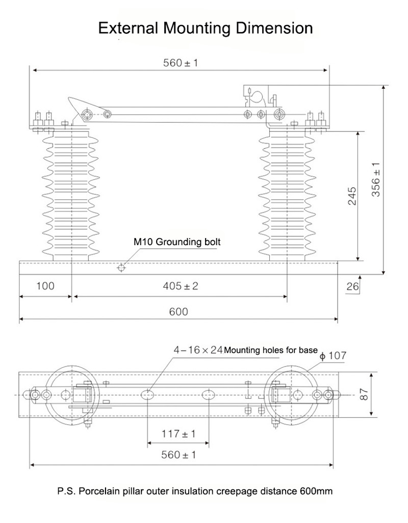
Structure:
This product is composed of base (plate), post insulator,
conductive part and interlock device. One end of the knife is
installed on the dynamic contact knife head through bolts, and the
other end of the knife is separately connected with the static
contact head, and each side is maintained in a good contact state
by the pressure of the compression spring. Each knife is
slot-shaped type, which not only increases the heat dissipation
surface of the knife, but also conducive to reducing the
temperature rise, and improve the mechanical strength of the knife,
making the dynamic thermal stability against short circuit. The
interlocking parts installed at the non-rotating end of the contact
knife and the static locking hook on the static contact constitute
the opening locking device, which is self-locking when the brake is
closed, so that the brake knife will not fall off by itself due to
its own weight or the action of electric power, resulting in the
opening of the brake without cause.
Safety Risks:
1.Electrical shock: High voltage disconnect switches can deliver a potentially lethal
electric shock if they are not handled properly. This can happen if
the switch is not properly isolated before it is opened or if there
is a fault in the equipment.
2.Arc flash: When high voltage disconnect switches are opened, an arc flash can
occur, which can release a significant amount of energy in the form
of heat, light, and pressure. This can cause burns, eye damage, and
other injuries.
3.Equipment failure: High voltage disconnect switches can fail if they are not properly
maintained or if they are overloaded. This can lead to equipment
damage, electrical fires, and other hazards.
4.Environmental hazards: High voltage disconnect switches are often located in outdoor
environments, where they can be exposed to extreme weather
conditions, such as high winds, heavy rain, and lightning strikes.
These conditions can create additional safety risks for personnel
who are operating or maintaining the equipment.
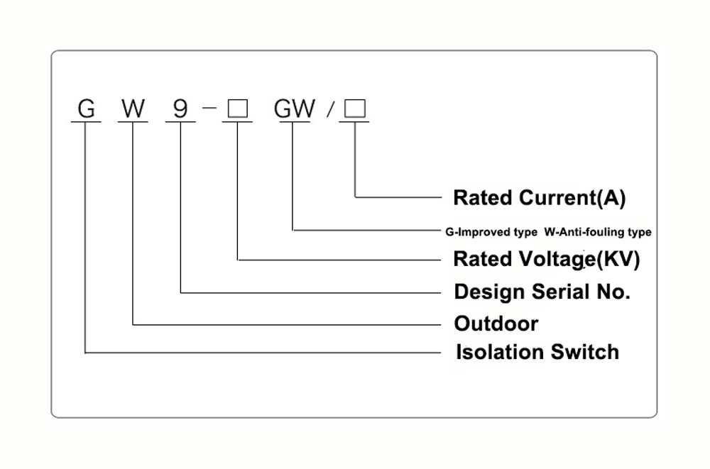
Technical Parameters:
| Serial No. | Parameter | Unit | Data | |||||||||
| 1 | Rated Voltage | kV | 12 | |||||||||
| 2 | Rated Current | Model No. | (H)GW9-12(W)/630-20 | A | 630 | |||||||
| (H)GW9-12(W)/1000-20 | 1000 | |||||||||||
| (H)GW9-12(W)/1250-31.5 | 1250 | |||||||||||
| 3 | 4s Short-time withstanding current | Model No. | (H)GW9-12(W)/630-20 | kA | 50 | |||||||
| (H)GW9-12(W)/1000-20 | 50 | |||||||||||
| (H)GW9-12(W)/1250-31.5 | 80 | |||||||||||
| 4 | Rated Insulation Level | Lightning surge withstand voltage(peak) | Polar-to-Earth (Positive & Negative) | kV | 75 | |||||||
| Interfracture (Positive & Negative) | 85 | |||||||||||
| Industrial frequency withstand voltage (1 min) (Effective value) | Dry Test/Wet Test | Polar-to-Earth | 42(Dry) 34(Wet) | |||||||||
| Interfracture | 48(Dry) | |||||||||||
| 48(Dry) | ||||||||||||
| 48(Dry) 40(Wet) | ||||||||||||
| 5 | Main Circuit Resistance | μ Ω | 630 | |||||||||
| 1000 | ||||||||||||
| 1250 | ||||||||||||
| 6 | Mechanical Life Time | times | 50 | |||||||||
| 50 | ||||||||||||
| 80 | ||||||||||||