|
|
[China]

Trade Verify
Contact name:Sherlin

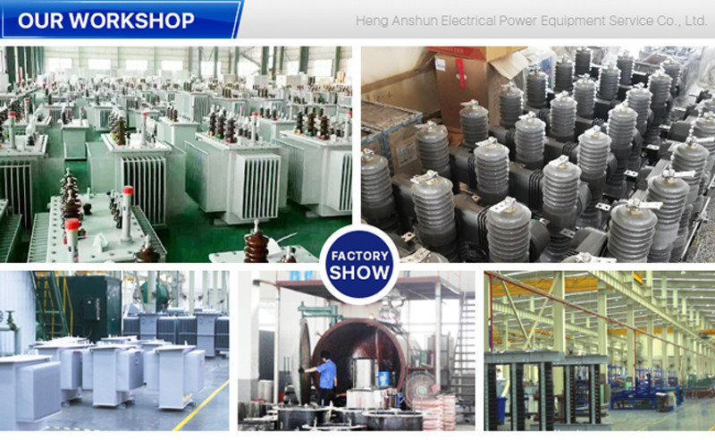
GuangDong Heng AnShun Electrical Power Equipment Service Co., Ltd. |
|
Verified Suppliers
|
|
|
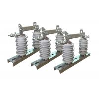
Industrial Outdoor Disconnector Switch For High Voltage Distribution System Easily Operated Hookstick Switch
Product Description:
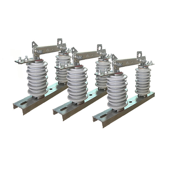
The outdoor disconnector switch, also referred to as an isolator
switch, is an indispensable component in high-voltage power
systems. Its primary purpose is to disconnect or isolate a specific
section of an electrical circuit from its power source.
The main function of the outdoor disconnector switch is to
physically break the electrical circuit, effectively separating the
equipment from the power source. This disconnection and isolation
allow maintenance personnel to work on the equipment safely,
minimizing the risk of electric shock.
It is important to note that unlike a vacuum circuit breaker, the
outdoor disconnector switch does not possess arc-quenching
capabilities. It is not designed to interrupt or extinguish
electrical arcs that may occur during circuit switching or fault
conditions.
In high-voltage power systems, the high-voltage isolator switch is
often coordinated with a vacuum circuit breaker. The circuit
breaker is responsible for detecting faults and tripping to
interrupt the current flow, while the disconnect isolator is
operated to physically isolate the circuit and provide a visual
indication of the disconnection.
The outdoor disconnector switch plays a critical role in ensuring
the safety of maintenance personnel. Prior to conducting any
maintenance work on electrical equipment, the disconnect isolator
is operated to open the circuit and create a visible air gap. This
action serves as confirmation that the equipment is de-energized
and safe for maintenance activities.
The outdoor disconnector switch, also referred to as a disconnect
switch or an isolator switch, is an indispensable component in
high-voltage power systems. Its primary purpose is to disconnect or
isolate a specific section of an electrical circuit from its power
source.
Application:
1.Circuit Isolation: High voltage isolator switches are used to isolate a section of a high voltage circuit for maintenance, repair, or testing purposes. By opening the switch, the section can be effectively disconnected from the rest of the system, allowing work to be carried out safely.
2.Load Switching: High voltage isolator switches can be used as load switches to control the flow of electrical power in a circuit. They are particularly useful in situations where the load is relatively small and does not require a circuit breaker or fuse.
3.Overhead Line Protection: High voltage isolator switches are often installed on overhead power lines to provide protection against lightning strikes and other electrical disturbances. By isolating a section of the line, the switch can help prevent damage to equipment and reduce the risk of power outages.
4.Transformer Protection: High voltage isolator switches are also used to protect transformers by isolating them from the electrical network in the event of a fault or overload. By opening the switch, the transformer can be disconnected from the network, preventing damage to the transformer and other equipment.
Operation:
1 Preparation: Before operating the switch, the circuit should be
de-energized and properly grounded to prevent any electrical
hazards. The switch should be inspected for any signs of damage or
wear and tear.
2 Closing the switch: To close the switch, the operator manually or
remotely moves the switch handle or control lever to the closed
position. This connects the circuit to the power source, allowing
current to flow through the circuit.
3 Opening the switch: To open the switch, the operator manually or
remotely moves the switch handle or control lever to the open
position. This disconnects the circuit from the power source,
interrupting the flow of current.
4 Arc management: When the switch is opened, an electrical arc may
occur between the contacts, which can be dangerous and cause damage
to the switch. To manage the arc, the switch may be equipped with
devices such as arc chutes or blowout coils.
5 Safety: Operators of high voltage disconnect switches must follow
proper safety procedures to prevent electrical hazards. This may
include wearing personal protective equipment, working in teams,
and following lockout/tagout procedures.
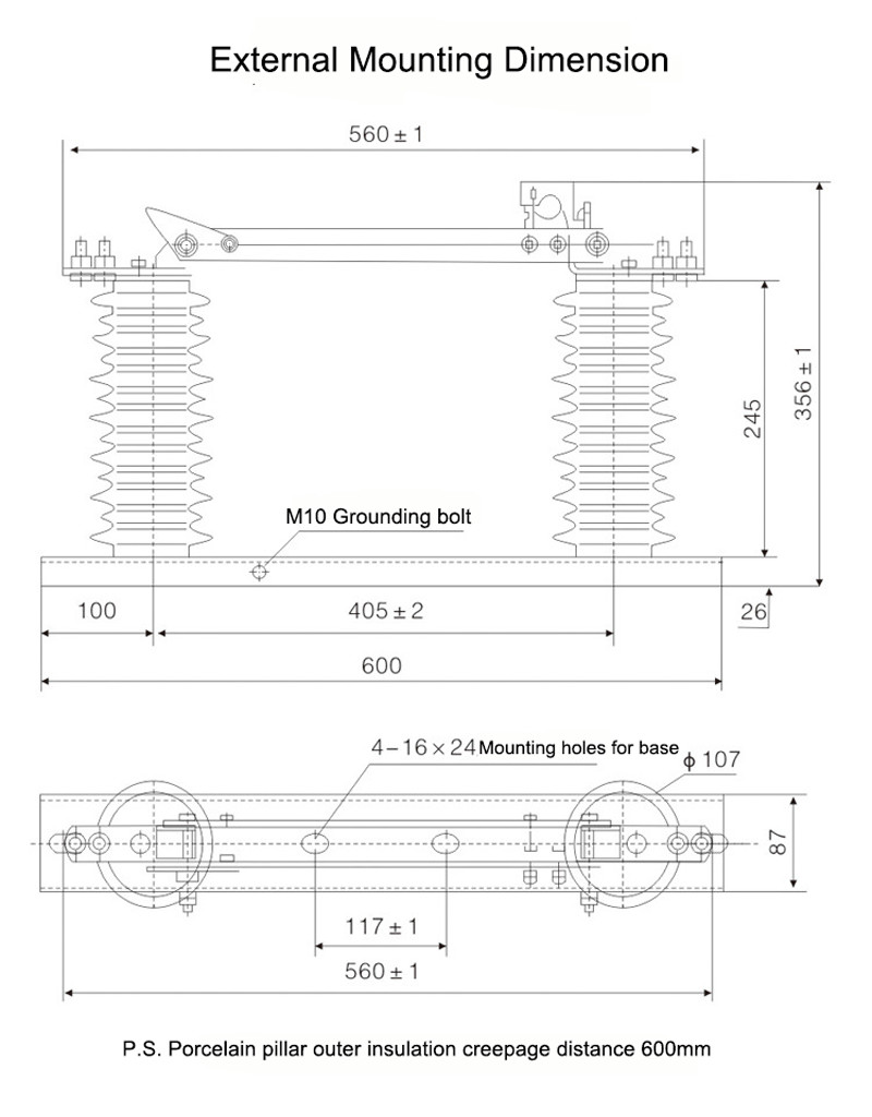
Structure:
The product being described is composed of a base (plate), post
insulator, conductive part, and interlock device. The knife is
installed on the dynamic contact knife head through bolts and is
separately connected with the static contact head. Each side is
maintained in a good contact state by the pressure of the
compression spring. The knife is a slot-shaped type, which
increases the heat dissipation surface and reduces the temperature
rise. This contributes to the mechanical strength of the knife and
makes it dynamically thermally stable against short circuits.
The interlocking parts installed at the non-rotating end of the
contact knife and the static locking hook on the static contact
form the opening locking device. When the brake is closed, the
device is self-locking, so the brake knife will not fall off due to
its own weight or the action of electric power, which could cause
the brake to open without cause.
This product is commonly used in power transmission and
distribution systems and plays a crucial role in ensuring the
proper functioning of the electrical grid. Proper safety procedures
should be followed when working with these switches, and only
qualified and trained personnel should be allowed to operate and
maintain them.
Condition:
1.The maximum altitude in the specified area does not exceed 1000 meters above sea level. This altitude limitation is relevant for the installation and operation of the equipment.
2.The ambient air temperature has certain limits. The maximum temperature should not exceed +40°C, and the minimum temperature can vary depending on the specific area. In general areas, the minimum temperature should not drop below -30°C, while in Paramos areas, it should not drop below -40°C.
3.The wind pressure should not exceed 700 Pascal (Pa), which corresponds to a wind speed of approximately 34 meters per second. This limit ensures that the equipment can withstand the force exerted by the wind without compromising its functionality or structural integrity.
4.The earthquake intensity should not exceed 8 degrees. This refers to the maximum intensity of seismic activity that the equipment can withstand without being damaged. The specific scale used to measure earthquake intensity may depend on the region or country.
5.The working environment should be free from frequent violent vibrations. This requirement ensures that the equipment remains stable and operational under normal operating conditions. Excessive vibrations can affect the performance and lifespan of the isolator.
6.Ordinary-type isolators should be installed in locations that are kept away from gas, smoke, chemical deposition, salt-spray fog, dust, and other explosive or corrosive substances. These materials can have detrimental effects on the insulation and conduction capabilities of the isolator, potentially compromising its performance and safety.
7.Pollution-proof type isolators are designed for use in areas with severe contamination. However, even in such areas, there should be no presence of explosive substances or materials that can cause fire. This requirement ensures that the isolator remains safe and functional despite the challenging environmental conditions.
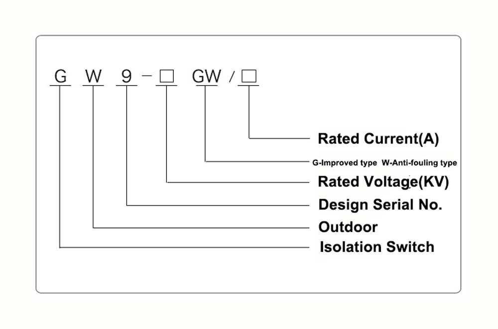
Technical Parameters:
| Serial No. | Parameter | Unit | Data | |||||||||
| 1 | Rated Voltage | kV | 12 | |||||||||
| 2 | Rated Current | Model No. | (H)GW9-12(W)/630-20 | A | 630 | |||||||
| (H)GW9-12(W)/1000-20 | 1000 | |||||||||||
| (H)GW9-12(W)/1250-31.5 | 1250 | |||||||||||
| 3 | 4s Short-time withstanding current | Model No. | (H)GW9-12(W)/630-20 | kA | 50 | |||||||
| (H)GW9-12(W)/1000-20 | 50 | |||||||||||
| (H)GW9-12(W)/1250-31.5 | 80 | |||||||||||
| 4 | Rated Insulation Level | Lightning surge withstand voltage(peak) | Polar-to-Earth (Positive & Negative) | kV | 75 | |||||||
| Interfracture (Positive & Negative) | 85 | |||||||||||
| Industrial frequency withstand voltage (1 min) (Effective value) | Dry Test/Wet Test | Polar-to-Earth | 42(Dry) 34(Wet) | |||||||||
| Interfracture | 48(Dry) | |||||||||||
| 48(Dry) | ||||||||||||
| 48(Dry) 40(Wet) | ||||||||||||
| 5 | Main Circuit Resistance | μ Ω | 630 | |||||||||
| 1000 | ||||||||||||
| 1250 | ||||||||||||
| 6 | Mechanical Life Time | times | 50 | |||||||||
| 50 | ||||||||||||
| 80 | ||||||||||||