

Active Member
|
[China]

Address: 803 Chevalier House, 45-51 Chatham Road South, Tsim Sha Tsui, Kowloon, Hong Kong
Contact name:Natalie Xue

Bicheng Technologies Limited |

|
|
RF-10 High Frequency Printed Circuit Board Taconic RF-10 10mil 20mil
60mil PCB Low Loss High DK RF PCB
(Printed Circuit Boards are custom-made products, the picture and
parameters shown are just for reference)
General Description
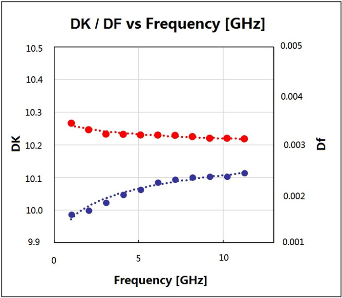
Taconic's RF-10 laminates are composites of ceramic filled PTFE and
woven fiberglass, which have the advantage
of high dielectric constant (10.2 10GHz) and low dissipation factor
(0.0025 10GHz). Thin woven fiberglass reinforcement
is used to offer both low dielectric loss and improved rigidity for
ease of handling and improved dimensional stability for
multilayer circuits.
RF-10 high frequency materials are engineered to provide a cost
effective substrates, responding to a need in RF
applications for size reduction. It bonds well to smooth low
profile copper too. The low dissipation combined with
the use of very smooth copper results in optimal insertion losses
at higher frequency where skin effect losses play
a substantial role.
Features Benefits
1. Excellent adhesion to smooth coppers

Typical Applications
1. Aircraft Collision Avoidance Systems
Our PCB Capability (RF-10)
| PCB Material: | Composites of Ceramic Filled PTFE and Woven Fiberglass |
| Designation: | RF-10 |
| Dielectric constant: | 10.2 |
| Dissipation Factor | 0.0025 10GHz |
| Layer count: | Double Sided PCB, Multilayer PCB, Hybrid PCB |
| Copper weight: | 0.5oz (17 µm), 1oz (35µm), 2oz (70µm) |
| PCB thickness: | 10mil (0.254mm), 20mil (0.508mm), 25mil (0.635mm), 60mil (1.524mm ), 125mil ( 3.175mm ) |
| PCB size: | ≤400mm X 500mm |
| Solder mask: | Green, Black, Blue, Yellow, Red etc. |
| Surface finish: | Bare copper, HASL, ENIG, Immersion silver, Immersion tin, OSP etc.. |
RF-10 Typical Values
| Property | Test Method | Unit | Value | Unit | Value |
| Dk @ 10 GHz | IPC-650 2.5.5.5.1 Mod. | 10.2 ± 0.3 | 10.2 ± 0.3 | ||
| Df @ 10 GHz | IPC-650 2.5.5.5.1 Mod. | 0.0025 | 0.0025 | ||
| TcK† (-55 to 150 °C) | IPC-650 2.5.5.6 | ppm/°C | -370 | ppm/°C | -370 |
| Moisture Absorption | IPC-650 2.6.2.1 | % | 0.08 | % | 0.08 |
| Peel Strength (1 oz. RT copper) | IPC-650 2.4.8 (solder) | lbs/in | 10 | N/mm | 1.7 |
| Volume Resistivity | IPC-650 2.5.17.1 | Mohm/cm | 6.0 x 10⁷ | Mohm/cm | 6.0 x 10⁷ |
| Surface Resistivity | IPC-650 2.5.17.1 | Mohm | 1.0 x 10⁸ | Mohm | 1.0 x 10⁸ |
| Flexural Strength (MD) | IPC - 650 - 2.4.4 | psi | 14,000 | N/mm2 | 96.53 |
| Flexural Strength (CD) | IPC - 650 - 2.4.4 | psi | 10,000 | N/mm2 | 68.95 |
| Tensile Strength (MD) | IPC - 650 - 2.4.19 | psi | 8,900 | N/mm2 | 62.57 |
| Tensile Strength (CD) | IPC - 650 - 2.4.19 | psi | 5,300 | N/mm2 | 37.26 |
| Dimensional Stability | IPC-650 2.4.39 (After Etch) | % (25 mil-MD) | -0.0032 | % (25 mil-CD) | -0.0239 |
| Dimensional Stability | IPC-650 2.4.39 (After Bake) | % (25 mil-MD) | -0.0215 | % (25 mil-CD) | -0.0529 |
| Dimensional Stability | IPC-650 2.4.39 (After Stress) | % (25 mil-MD) | -0.0301 | % (25 mil-CD) | -0.0653 |
| Dimensional Stability | IPC-650 2.4.39 (After Etch) | % (60 mil-MD) | -0.0027 | % (60 mil-CD) | -0.0142 |
| Dimensional Stability | IPC-650 2.4.39 (After Bake) | % (60 mil-MD) | -0.1500 | % (60 mil-CD) | -0.0326 |
| Dimensional Stability | IPC-650 2.4.39 (After Stress) | % (60 mil-MD) | -0.0167 | % (60 mil-CD) | -0.0377 |
| Density (Specific Gravity) | IPC-650-2.3.5 | g/cm3 | 2.77 | g/cm3 | 2.77 |
| Specific Heat | IPC-650-2.4.50 | J/g°C | 0.9 | J/g°C | 0.9 |
| Thermal Conductivity (Unclad) | IPC-650-2.4.50 | W/M*K | 0.85 | W/M*K | 0.85 |
| CTE (X -Y axis) (50 to 150 °C) | IPC-650 2.4.41 | ppm/°C | 16-20 | ppm/°C | 16-20 |
| CTE (Z axis) (50 to 150 °C) | IPC-650 2.4.41 | ppm/°C | 25 | ppm/°C | 25 |
| Flammability Rating | Internal | V-0 | V-0 |


