|
|
[China]

Trade Verify
Address: Address:Room624,Fangdichan development building,Guicheng south,Nanhai,Foshan,China
Contact name:Tracy

ONESEINE TECHNOLOGY CO.,LTD |
|
Verified Suppliers
|

|
|
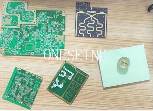
Rogers 3010 Material Ifb Microwave Oven PCB RF Circuit Board
PCB quick details:
Material:Rogers 3010
PCB size:290*120MM
Layer:2
RF pcb samples are provided
Surface finish:ENIG
Copper weight:0.5OZ
When designing microwave PCBs, it's important to be aware of and comply with relevant electromagnetic interference (EMI) and electromagnetic compatibility (EMC) standards. Here are some common standards that are often applicable to microwave PCB design:
1. FCC Part 15: The Federal Communications Commission (FCC) Part 15 governs the unintentional radiators, including the limits for conducted and radiated emissions. It sets the limits for electromagnetic emissions from electronic devices to prevent interference with other equipment.
2. CISPR 22/EN 55022: CISPR 22, also known as EN 55022, specifies the limits and methods of measurement of radio disturbance characteristics for information technology equipment (ITE). It covers both radiated and conducted emissions.
3. CISPR 11/EN 55011: CISPR 11, or EN 55011, focuses on industrial, scientific, and medical (ISM) equipment. It sets the limits and measurement methods for electromagnetic emissions from ISM equipment, including microwave devices.
4. CISPR 25: CISPR 25 addresses the electromagnetic compatibility of vehicles, including their sub-assemblies and components. It specifies the limits and measurement methods for conducted and radiated emissions from vehicles, including those equipped with microwave-based systems.
5. IEC 61000-4-x: The IEC 61000-4-x series of standards provides a comprehensive framework for testing and measuring various aspects of EMC. Relevant parts of this series include IEC 61000-4-2 (electrostatic discharge), IEC 61000-4-3 (radiated immunity), IEC 61000-4-4 (electrical fast transient/burst), IEC 61000-4-5 (surge immunity), and IEC 61000-4-6 (conducted immunity), among others.
6. MIL-STD-461: MIL-STD-461 is a U.S. military standard that specifies the electromagnetic compatibility requirements and test methods for military equipment. It covers conducted and radiated emissions, as well as susceptibility to external electromagnetic fields.
7. RTCA DO-160: RTCA DO-160 is a set of environmental test procedures and conditions for avionics equipment. It includes sections related to EMI/EMC testing, such as conducted emissions, radiated emissions, and susceptibility to electromagnetic fields.
These are just a few examples of the commonly referenced EMI/EMC standards. The specific standards applicable to your microwave PCB design will depend on the intended application, industry, and geographical location. It's important to research and identify the relevant standards for your specific case and ensure compliance during the design and testing phases.
Please note that standards can be updated or revised over time, so it's important to stay updated with the latest versions and any amendments or regional variations that may apply to your project. Consulting with EMC specialists and testing laboratories can help ensure compliance with the appropriate standards for your microwave PCB design.
Popular Materials for RF PCB and Microwave PCB
Oneseine RF PCB material
Rogers RO4003C, RO4350B, RO4360, RO4533, RO4535, RO4730, RO4232, RO4233, RO3003, RO3006, RO3010, RO3035, R03203, RO3206, RO3210, RO3730, RO5780, RO5880, RO6002, RO3202, RO6006
Taconic TLY-5A, TLY-5, TLY-3, HT1.5, TLX-0, TLX-9, TLX-8, TLX-7, TLX-6, TLC-27, TLE-95, TLC-30, TPG-30, TLG-30, RF-30, TSM-30, TLC-32, TPG32, TLG-32, TLG-34, TPG-35, TLG-35, GF-35, RF-35, RF-35A, RF-35P, RF-41, RF-43, RF-45, RF-60A, CER-10
Arlon AD255 C03099, AD255 C06099, AD255 C04099, AD300 C03099, AD300 C04099, AD300 C06009, TC600, AD250 C02055C, TC350, MCG300CG, DCL220, CUCLAD 217LX, CUCLAD 250GX, ARLON 55NT
Wangling, Taixing F4BK225, F4BK265, F4BK300, F4BK350, F4BM220, F4BM255, F4BM265, F4BM300, F4BM350
For a successful Radio Frequency (RF) PCB manufacturing process, you should adopt strict design, fabrication and assembly procedures.
It is the only way to avoid possible crosstalk, maintain signal integrity, prevent possible component failure, and many more.
Today’s guide captures all the basic and advanced aspects of RF PCB design and fabrication.
Let’ get started.
RF PCB Design Basics
Benefits of RF printed circuit boards
RF PCB Layout Guidelines
RF PCB Design Considerations
RF PCB Design Software
RF PCB Material
Component Sourcing for RF Printed Circuit Board Design
Classification of Radio Frequency Printed Circuit Board Design
RF printed circuit board Manufacturing Process
RF PCB Design Quality Standards and Regulations
Conclusion
Microwave pcb concept:
A microwave PCB, also known as a microwave printed circuit board, is a specialized type of circuit board used in microwave devices and systems. It is designed to handle high-frequency signals and is optimized for microwave applications.
Here are some key points about microwave PCBs:
1. High-Frequency Design: Microwave PCBs are specifically designed to handle high-frequency signals in the microwave range, typically ranging from 300 MHz to several gigahertz (GHz). These boards are engineered to minimize signal loss, maintain controlled impedance, and minimize electromagnetic interference (EMI) at high frequencies.
2. Material Selection: Microwave PCBs are typically made using specialized high-frequency materials that have low dielectric loss and good electrical properties at microwave frequencies. Common substrate materials include ceramic-filled PTFE (Polytetrafluoroethylene), such as Rogers, Taconic, or Arlon, as well as other materials like FR-4 with specific high-frequency characteristics.
3. Controlled Impedance: Maintaining controlled impedance is critical in microwave circuits to ensure signal integrity and minimize reflections. Microwave PCBs utilize controlled impedance traces and transmission lines to match the characteristic impedance of the system, allowing for efficient signal transmission.
4. Design Considerations: Designing a microwave PCB involves careful consideration of various factors, such as trace widths, spacing, via placement, and component placement. High-frequency simulation tools, such as electromagnetic field solvers, are often used to analyze and optimize the design for performance.
5. RF Connectors: Microwave PCBs often incorporate specialized connectors designed for high-frequency applications. These connectors, such as SMA (SubMiniature version A) or SMP (SubMiniature Push-On), provide good RF performance and low signal loss.
6. Grounding and Shielding: Proper grounding and shielding techniques are crucial in microwave PCB design to minimize noise and interference. Ground planes and shielding layers are employed to provide effective isolation and reduce electromagnetic coupling between components and traces.
Microwave PCBs are commonly used in various applications, including microwave communication systems, radar systems, satellite communication systems, wireless networks, and high-frequency test equipment.
It's important to note that designing and manufacturing microwave PCBs require specialized knowledge and expertise due to the unique challenges posed by high-frequency applications. If you are looking to work with microwave PCBs, it's recommended to consult with experienced PCB designers and manufacturers with expertise in high-frequency and microwave design.