
|
|
[China]

Trade Verify
Address: R102, #24 Huangcun East Road,Tianhe District, Guangzhou 510660
Contact name:Jack Zhou

Guangzhou UC Instruments., Co. Ltd. |
|
Verified Suppliers
|
|
|
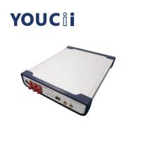
UC9710B Full Rate 10Gbps CDR Clock Recovery Module Adaptive rate
UC9710 CDR (Clock Recovery Module ) is mainly used to provide clock
recovery signal in the test environment without triggering clock,
so as to use the sampling oscilloscope to test the optical eye
diagram of the device. The typical application is the testing of
optical network equipment or the BOB product in PON application.
Because the photometric device itself has no frequency division
clock output, it is necessary to recover the clock signal to
trigger the sampling oscilloscope when testing the optical eye
diagram.
UC9710 CDR has a SFP optical port, which is suitable for SFP
encapsulated conventional SFP, SFP+, OLT SFP and other optical
modules. It only needs the receiving end of the optical module to
convert the optical signal to the electrical signal, and then
extract and output the clock of the electrical signal. Clock signal
is mainly used for the trigger signal of oscilloscope. This device
self-adapts to the rate and does not require software
configuration.
Specification
| No. | Specifications | Max. | Min. | Unit. |
| 1 | Data rate range | 11.3 | 0.155 | Gbps |
| 2 | Wavelength range | 1600 | 800 | nm |
| 3 | Optical input range (determined by module sensitivity) | +3 | -15 | dBm |
| 4 | Output recovered electrical clock range | 5.65 / 2.825 | 0.0775/0.03875 | GHz |
| 5 | Output electrical clock amplitude | 600(typical value) | mVpp | |
| 6 | Clock rise time(OC-192)(20%~80%) | 33.1 | 22.2 | ps |
| 7 | Clock fall time(OC-192)(80%~20%) | 33.7 | 23.9 | ps |
| 8 | Output Jitter(10.3125Gbps) | 1 (typical value) | ps | |
| 9 | Clock frequency(10.3125Gbpsrate, divided by2/4) | 5.156 / 2.578 | 5.156 / 2.578 | GHz |
| 10 | Internal Loss of Signal Detect (LOS) | 128 (overload) | 5 (sensitivity) | mV |
| 11 | Power supply voltage (input voltage of external power supply) | 5.5 | 4 | V |
| 12 | Operating temperature | 85 | -40 | ℃ |
When sampling oscilloscope tests optical eye pattern
and waveform, it needs to be triggered by the same source as the
measured signal. CDR (clock recovery) module is mainly used in the
test environment that requires sampling oscilloscope to test
optical eye map, but does not provide trigger clock. Typical
application is the test of optical network equipment, or for BOB
products in PON application, because the measured optical equipment
itself does not have a frequency division clock output. The clock
signal needs to be recovered to trigger the sampling oscilloscope
when testing the optical eye pattern.
This CDR is equipped with an SFP optical port, which
can be connected to the conventional SFP, SFP+, OLT SFP and other
optical modules encapsulated in SFP. Only the receiving end of the
optical module is needed, which is responsible for converting
optical signals into electrical signals, and then the instrument
extracts and outputs the clock of electric signals. The clock
signals are mainly used for triggering signals of oscilloscope.


