

Active Member
|
[China]

Address: Room 36B1-B2, Building C, Electronics Science & Technology Building Shennan Mid-Road, Shenzhen China
Contact name:Sharon Yang

Anterwell Technology Ltd. |

|
|
TYPICAL APPLICATION
 DESCRIPTION
The MP1593 is a step-down regulator with an internal Power MOSFET. It achieves 3A of continuous output current over a wide input supply range with excellent load and line regulation.
Current mode operation provides fast transient response and eases loop stabilization.
Fault condition protection includes cycle-by-cycle current limiting and thermal shutdown. An adjustable soft-start reduces the stress on the input source at startup. In shutdown mode the regulator draws 20µA of supply current.
The MP1593 requires a minimum number of readily available externa components, providing a compact solution.
 APPLICATIONS
• Distributed Power Systems
• Battery Chargers
• Pre-Regulator for Linear Regulators
• Flat Panel TVs
• Set-Top Boxes
• Cigarette Lighter Powered Devices
• DVD/PVR Devices
FEATURES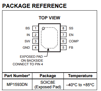
• 3A Output Current
• Programmable Soft-Start
• 100mΩ Internal Power MOSFET Switch
• Stable with Low ESR Output Ceramic Capacitors
• Up to 95% Efficiency
• 20µA Shutdown Mode
• Fixed 385KHz Frequency
• Thermal Shutdown
• Cycle-by-Cycle Over Current Protection
• Wide 4.75V to 28V Operating Input Range
• Output Adjustable from 1.22V
• Under-Voltage Lockout
• Available in 8-Pin SOIC Package
ELECTRICAL CHARACTERISTICS (continued) VIN = 12V, TA = +25°C, unless otherwise noted.
| Parameter | Symbol | Condition | Min | Typ | Max | Units |
| EN Threshold Voltage | 0.9 | 1.2 | 1.5 | V | ||
| Enable Pull Up Current | VEN = 0V | 1.0 | 1.7 | 2.5 | µA | |
| Under-Voltage Lockout Threshold | VIN Rising | 2.3 | 2.6 | 2.9 | V | |
| Under-Voltage Lockout Threshold Hysteresis | 210 | mV | ||||
| Soft-Start Period | CSS = 0.1µF | 10 | ms | |||
| Thermal Shutdown | 160 | °C |
Feedback Voltage vs Temperature Peak Current Limit vs Temperature

Soft-Start Waveforms Turn Off Waveforms

OPERATION

Figure 1—Functional Block Diagram
The MP1593 is a current-mode step-down regulator. It regulates input voltages from 4.75V to 28V down to an output voltage as low as 1.22V, and is able to supply up to 3A of continuous load current.
The MP1593 uses current-mode control to regulate the output voltage. The output voltage is measured at FB through a resistive voltage divider and amplified through the internal error amplifier. The output current of the transconductance error amplifier is presented at COMP where a network compensates the regulation control system. The voltage at COMP is compared to the internally measured switch current to control the output voltage.
The converter uses an internal N-Channel MOSFET switch to step-down the input voltage to the regulated output voltage. Since the MOSFET requires a gate voltage greater than the input voltage, a boost capacitor connected between SW and BS drives the gate. The capacitor is internally charged when SW is low.
An internal 10Ω switch from SW to GND is used to insure that SW is pulled to GND when it is low to fully charge the BS capacitor.


