12-36VDC Max power 500W Arduino control JYQD-V7.3E2 Hall effect
BLDC motor driver board
Application guidelines
1. Please confirm that the voltage and power parameters of the
motor not exceed the range as specified.
2. This BLDC motor driver applicable to hall effect brushless
dc motor with Hall at 120°, not all manufacturers' Hall line
sequence are corresponding, you can adjust the Hall line sequence
or motor three-phase line sequence according to the actual
situation, to achieve the best driving effect.
3. JYQD-V7.3E2 is the driver board without housing and heatsink, it
can drive the BLDC motor below 100 watt without any heatsink, but
needs normal ventilation.please add heatsink if the power more than
100W.
4. Please do pay attention to the insulation between the
BLDC motor driver MOSFET and the heatsink or the installation
plate.
Wiring diagram
1. Control port
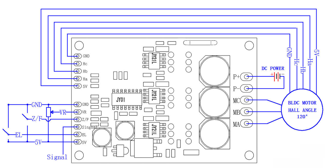
5V —Driver board internal output voltage, external potentiometer or
switch for speed adjustment and reversing operation |
Z/F —Rotating direction control ports. Connect “5V” high level or
no connect is Forward direction, connect 0 V low level or connect
to GND is reverse direction. |
VR —Speed control port. Analog voltage linear speed regulation 0.1v
-5V, The input resistance is 20K Ohm ,connect with GND when input
PWM speed regulation, PWM frequency:1-20KHZ; Duty cycle 0-100% |
EL —Enable port control. Connect 5V or no connect to allow
operation, connect GND to forbid operation. |
Signal— Speed pulse signal output |
GND—Used for Driver board internal control |
2. Power port
MA ----BLDC motor phase A
MB ---- BLDC motor phase B
MC---- BLDC motor phase C
P- ----Power DC-
P+----Power DC +
3:Hall sensor port
Ha--- Hall a
Hb---Hall b
Hc---Hall c
GND---GND
5V---5V output
Dimensional drawing
DOWNLOAD JYQD-V7.3E2 USER MANUAL