

Active Member
|
[China]

Address: Dongli Road, Donglai Village, Yangshe Town, Zhangjiagang City, Suzhou, Jiangsu, China
Contact name:Kira Geng

Jiangsu Zhongyin Machinery Co.,Ltd |
|
|
The transition wheel adopts the steel dial bottle opening, which does not need to adjust the height of the bottle.
The bottle puller adopts the bottom transfer mode, and the bottom plate of the bottle is a spiral descending curve. The shape of the bottle is not required to adjust the height of the machine and the delivery chain.
The dial has a bottle protector.
The rotating discs are all made of stainless steel.
Large flat-toothed bearings for smooth and reliable operation.
The filling method is gravity filling.
With a ring type cylinder, the liquid level of the cylinder is controlled by a float.
The filling valve is made of high quality stainless steel.
Each filling valve is provided with a return air passage independent of the liquid cylinder, and the displaced air in the PET bottle does not enter the liquid cylinder during the filling process.
The addition of the return air passage also realizes the control of the filling amount in the bottle, corrects the filling liquid level, and realizes the control of the high-precision filling liquid level.
High-speed, high-precision liquid level filling valve, flow rate up to 200ml / s, liquid level accuracy ≤ ± 2mm.
The filling valve is equipped with a cleaning cup for thorough CIP circulation cleaning of the filling valve.
The lifting cylinder bottle lifting mechanism is adopted, and the bottle mouth is clamped by the bottle holder, and the bottle shape is changed without changing and adjusting any parts.
The magnetic torque capping head is used, the screw cap effect is stable and reliable, and the defective rate of capping is ≤0.2%.
The falling cap rail is provided with a reverse cap preventing and reverse cap removing mechanism, and a set of photoelectric switches is installed at the same time. When there is no cap on the falling cap rail, the machine operation is automatically stopped, and the appearance of the uncaped bottle can be effectively avoided.
There is a capping machine detection switch, which is connected with the lock cap cylinder at the junction of the falling cap rail and the dial plate to control the discharge of the cap, to ensure that the cap is stopped when there is no bottle, and the loss of the cap is reduced.
Efficient centrifugal cap method, the cap wear is small.
The cap sorter is equipped with a cap detection mechanism for controlling the start and stop of the cap lift.
The drive motor adopts frequency conversion speed regulation, which is synchronized with the blow-filling and rotary machine to prevent the bottle from falling over.
The photoelectric switch is installed on the delivery conveyor chain. When the bottle is blocked, the blow-drying machine can be controlled to decelerate and stop.
The frame is welded from high-quality carbon steel, and is surface-treated and sprayed. The surface is caped with stainless steel.
Exclusive use of stainless steel countertop through-hole tensile structure, with O-ring seals, so that leakage of all the bearing seats and support shafts on the table surface may be reduced to zero.
The whole machine adopts PLC control, which automatically completes the whole process control of the blowing and filling machine from the bottle to the bottle.
Production speed, shift output count, fault category, fault occurrence point, etc. are displayed on the screen. And can automatically count the time of failure, fault category and other information.
This machine is equipped with automatic centralized lubrication
pump controlled by PLC. Each lubrication point can be used for
regular quantitative refueling, which improves the operational
reliability of the equipment.
....,,.,.,,,,,.,.
The bottle is transferred to the filling machine via the transition
wheel. The bottle entering the filling machine is held by the bottleneck
holder stuck in the bottle mouth. The filling valve is lowered and raised by the valve lifting
mechanism under the action of the cylinder. Filling is done by pressure filling. After the filling valve is lowered into contact with the bottle
mouth, the filling process is completed. After the filling is
completed, the filling valve rises out of the bottle mouth, and the
bottle enters the capping machine through the card bottleneck
transition dial. The anti-rotation knife on the capping machine catches the bottle
neck and keeps the bottle upright and prevents rotation. The anti-rotation knife on the capping machine catches the bottle
neck and keeps the bottle upright and prevents rotation. The anti-rotation knife on the capping machine catches the bottle
neck and keeps the bottle upright and prevents rotation.
:
The whole machine drive is as follows:
,7.5kW.
The motor uses a Lenze brand motor with a power of 7.5 kW.
:GKS09-3A HAK 19SC17/MCA19S17-RSOBO
The reducer is a turbine reducer: GKS09-3A HAK
19SC17/MCA19S17-RSOBO
m = 4
Gear modulus m = 4
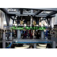
Model | CGX8-40-10 | |
Number of heads | 40 10 heads of filling 8 heads of sealing | |
Capacity | 18000/(600ml/) 18000B/H (600ml/B) | |
Applicable bottle type | Bottle diameter range | 50~100mm |
Bottle height range | 100~320mm | |
| Air pressure | 0.7MPa | |
| (AC) Working voltage (AC) | 380V | |
| (DC) Control voltage (DC) | 24V | |
Main motor power | 7.5KW | |
Total power | 8.5KW | |
Dimensions | 6500X4500X2800 | |
Total Weight | 8500kg | |
,,,,,,,;;,.
The filling machine is mainly composed of a supporting component, a
cylinder lifting device, a liquid inlet component, a liquid
returning component, a valve lifting device, a bearing component, a
dummy cup, a transmission component, etc., and functions to fill
the material into the bottle in the device. The parts in contact
with the materials are made of stainless steel and special
materials, which meet the food hygiene requirements.
2)Filling time allocation table
| No | Station | Angle | ()Time (s) |
| 1 | Empty travel | 62.04 | 1.05 |
| 2 | Valve rise | 27.5 | 0.49 |
| 3 | Valve drop | 76.46 | 1.21 |
| 4 | Filling | 194 | 3.25 |
| 5 | Every lap time | 360 | 6 |
:18000BPH(600ml/) Production capacity: 18000BPH (600ml / bottle)
:3.25Filling time: 3.25 seconds
,.
The lifting and lowering of the bottle is realized by the cylinder
lifting device driving the bottle lifting device, and the pulling
down cam ensures that the filling valve can return to the original
position.
,,,,3,1,2,4,5
The components shown in the figure below are the transmission
components, which mainly function as transmission and load, 3 is
the slewing bearing, 1, 2, 4 are the transmission gears, and 5 is
the bearing housing.
:The structure of the valve is as follows:
:1. 2. 3. 4. 5. 6. 7. 8. 9. 10. 11. 12. 13. 14.
No. Description: 1. Spool 2. Retaining ring 3. Upper valve seat 4.
Leather bowl 5. Lower valve seat 6. Sliding sleeve 7. Compression
spring 8. Upper valve body 9. Lower valve body 10. Sealing pressure
ring 11. Air return pipe 12. Bottle mouth gasket 13. Seal ring 14.
Seal ring
working principle
:The installation structure of the valve is as follows:
:The working process of the valve is as follows:
,,,,,,,,,,,,,.
When the bottle enters the filling machine, the cylinder drives the
bottle upward to open the filling valve. At this time, the liquid
in the liquid cylinder enters the bottle under the action of
gravity, and the air in the bottle enters the switching handle
through the center return pipe and enters the cylinder. When the
bottle is filled, the bottle is lowered by the cam, and the bottle
leaves the mouth mat, the valve is closed, but the return pipe is
also inserted into the bottle. At this time, the switching handle is switched to the vacuum
chamber, and the water above the return pipe in the bottle is
pumped into the vacuum chamber, and the position of the return pipe
end is the height of the liquid level, and the liquid level in the
bottle can be freely set by adjusting the length of the return
pipe. height.
:Fast water line valve features:
Filling method is gravity filling
High-speed, high-precision liquid level, flow rate up to 200ml/s, liquid level accuracy ≤±2mm
Each filling valve is equipped with 2 return air passages, 1 into the cylinder, 1 into the vacuum chamber, and switch between the filling process.
The filling valve is equipped with a cleaning cup for thorough CIP
circulation cleaning of the filling valve
,,,,,.
The capping machine is composed of a capping machine base, a
transition gear device, a capping device, a base and a
transmission, an anti-rotation column, a lifting device and the
like.
,,.
The drive of the capping machine is transmitted to the gear by the
reducer, and the power is transmitted to the capping head through
the lifting column, and at the same time, the excessive gear is
rotated to drive the rotation of the dial plate.
,,,,,.
The up and down movement of the capping head is realized by the
capping cam. The capping cam is fixed and non-rotating. The cap is
fed to the capping ring of the capping cap through the capping rail
and then the capping disc. When there is a bottle, the cap is
followed by The rotation of the capping head is simultaneously
moved downward, and the cap is screwed onto the thread of the
bottle mouth.
Rotation and rotation
,.
On the one hand, the capping head rotates with the main body, and
on the other hand, it is rotated by the ring gear.
,,,,,,.
Up and down movement
The cam is fixed to the top plate. Therefore, the cam is
stationary. When the frame rotates, the roller mounted on the
sliding sleeve rolls along the working surface of the cam, so that
the sliding sleeve moves up and down to realize the up and down
movement of the capping head.
1,,,.,,.
The shaft 1 is rotated by the action of the power belt. When the
capping machine rotates one revolution, each shaft reciprocates up
and down once. The cam controls the up and down movement of the
shaft, and the cam is mounted on the fixed portion of the upper
portion of the capping machine.
,.,.
When the bottle is transferred from the filling machine, the
capping head has taken a cap from the dial pan. The shaft descends
under the action of the cam guide, and the rear thrust ring
performs a capping operation.
,,,,,,1,,,.,,.,22~6mm,3,.
The upper cap of the capping head is screwed tightly on the sliding
sleeve mouth. When the sliding sleeve is rotated, rotated, moved up
and down, the capping head also performs corresponding synchronous
movement, and two sets of adjacent magnetic opposite magnetic
columns are installed in the capping head. 1, through the phase
suction of the magnetic body to ensure the corresponding capping
torque, the size of the capping torque is ensured by adjusting the
distance between the two sets of magnetic bodies. When the capping torque exceeds a fixed value, the relative sliding
between the two sets of magnets is used to achieve the rotation
stop of the capping ring gear. The magnet adjusting ring in the capping head is provided for the
downward force of the cap, and the capping die 2 is allowed to
compress 2 to 6 mm in the axial direction during operation. The cap
spring 3 is for preventing the bottle and removing the bottle in
the capping mold. Cap to ensure the machine is running normally.
:4,5,.
Note: The magnet adjustment ring 4 and the top cap rod 5 in the
capping head have been adjusted at the factory. Please do not
adjust it easily.
,:1,2.48.
The lifting device is used to adjust the capping machine, which is
manually operated: loosen the screw 1 and manually adjust the hand
wheel 2. The bearing here is added with lithium or calcium grease
once every 48 hours.
:,.
Note: The height has been adjusted at the factory, please do not
adjust it easily.
,1,2,34..4,5.
The base mainly supports the capping machine, and the power is
transmitted to the gear through the gear 1, the sleeve 2 and the
flange 3 to drive the capping machine to rotate. The power of the
dial assembly also stems from this. Parts 4, 5 support the entire
weight of the capping machine.
,
The function of the dial cap assembly is to properly distribute the
cap that is handled by the cap under the capping head, and transmit
power from the pin teeth between the capping machine and the dial
cap assembly.
,,,,,,.,.
The capping device mounted on the upper part of the capping machine
drives the rotating disc to rotate by the speed reducer, so that
the cap leaves the capping device from the capping port under the
action of centrifugal force, and a positive and negative cap
separating device is arranged at the outlet, when the anti-cap is
passed, The cap automatically falls into the return pipe, and the
reverse cap is automatically blown back to the cap device by the
wind, and only the front cap can smoothly enter the cap rail. The
number of caps in the cap device is controlled by the proximity
switch to automatically control the cap machine to ensure the best
effect of the lower cap.
.,,.,,.
When the front cap enters the cap rail, it can smoothly enter the
dial plate. To prevent accidents, an anti-reverse cap dial is also
placed on the cap rail to ensure that the cap that enters the dial
tray is correct. A pair of photoelectric switches are also arranged
on the falling cap rail, and when no cap is detected, the host must
be stopped.
,,1,;2,;3,..
The function of the bottle puller in the whole machine is to
transfer the semi-finished product of filling and capping to the
conveyor chain frame, 1 is the bottle body guide plate, guiding the
role; 2 is the bottom plate of the bottle, ensuring that the bottle
can be lowered to the chain frame The height of the bottle is the
role of the bottle. Power is supplied by the gears under the
workbench.
,,,.;,,;,,;,.
The function of the bottle chain frame is to transport the finished
product which has been washed, filled and capped to the subsequent
packaging link, and the power is provided by the rear conveyor
chain frame. The bottle chain frame is installed on the
three-in-one machine table; since the device is transported to the
bottom of the bottle, when the bottle type is changed, the height
of the bottom of the bottle is constant; the length of the bottle
is short and short, and the chain frame does not need to be
adjusted in height; If the bottle diameter changes, adjust the
spacing of the rails on both sides of the bottle.
,,,;,,,.
Sealing the window in the whole machine to prevent the person from
touching the rotating part of the machine during the operation, and
also preventing the liquid which may have a stimulating effect such
as the scouring medium from sticking to the skin of the person to
avoid unnecessary damage; There is an observation window on the
sealing window. The personnel can observe the operation of the
whole machine outside, and can open the sealing window into the
inside of the machine during maintenance and repair.


