
|
|
[China]

Trade Verify
Address: RM C, 13/F, HARVARD COMMERCIAL BUILDING, 105-111 THOMSON ROAD, WAN CHAI, HK
Contact name:Lynette Wong

KingPo Technology Development Limited |
|
Verified Suppliers
|
|
|
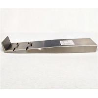
Wedge probe , IEC 62368-1 Figure V.4 – Wedge probe
According to standard: IEC62368-1
Material :heat-treated steel
Length :300mm
Width :50mm
Bendable Section :30/30/40mm
Calibration Certificate:Figure V.4 Wedge probe.pdf


Packaging and Shipping
1. Aluminium box and carton box, careful and tight package, make
sure the package is intact.
2. The package will be shipped by DHL/Fedex/TNT/EMS/UPS/China post/EF-Express/Special line, as you have chose in the order.
3. The shipping time is different, it depends on the distance bewteen us. At usual, exclude the preparing time, the goods would be sent to you in 5 days.


IEC 62368-1:2018-10
TESTING AND MEASURING EQUIPMENT/ALLOWED SUBCONTRACTING
Clause
| Measurement/testing | Testing / measuring equipment / material needed | Subcontracting | ||
| 4.1.4 | Equipment Installation (Outdoor), Conditioning | Test chamber: minimum range of –33°C to +40°C. | ROUT | ||
| 4.7 | Equipment for direct insertion in to mains socket-outlets | Test equipment (see Fig. 11 of IEC 60065)
| RB | ||
| 4.8 | Coin/button cell batteries | 30 N ± 1N applied by rigid test finger (Figure V.1); test hook (Figure 20); calliper; timer | RB | ||
| Crush Test (330 N ± 5N); flat surface measuring 100 mm by 250 mm; timer; air | RB | ||||
| Torque gauges, test hook | RB | ||||
| 5.2.2.2 | Steady- state voltage and current limits | Ampere- and voltmeter suitable for the current and waveform, frequency meter Measuring instruments in according to IEC 60990: 1999 Figure 4 and 5, timer, 2 kW resistor | RB | ||
| 5.2.2.4 | Single pulse limits | Oscilloscope | RB | ||
| 5.3.2. | Accessibility to electrical energy sources and safeguards | Test probes V1, V2, V3, V4, V5; T.3, calliper, hipot | RB | ||
| 5.4.1.4, 9.2.5, Annex E | Maximum operating temperatures for materials, components and systems | Voltage supply | Single phase voltage supply systems/variability/adequacy | RB | |
| Three phase voltage supply systems | S | ||||
| Temperature (rise) | Temperature recorder (multi-channel) | RB | |||
| Thermocouples | RB | ||||
| Winding resistance (normally > 1,0 W 2-wire, 4-wire <1,0 W ). | RB | ||||
| Voltage | Voltmeters (ac/dc) | RB | |||
| High voltage meter (probe) | RB | ||||
| Current | Currents (ac/dc) | RB | |||
| Loading | Loads (resistive) | RB | |||
| 5.4.1.5.3 | Thermal cycling test procedure | Annex G 13.6.2 Full draught oven (± 2ºC) Cooling facility (0º±2 C) Scratch test device with steel pin | S | ||
| 5.4.1.10 | Thermoplastic parts on which conductive metallic parts are directly mounted | Vicat test B 50 of ISO 306 | S | ||
| Ball pressure test apparatus according to IEC 60695-10-2, Oven at least 125ºC ± 3°C | RB | ||||
5.4.2, 5.4.3, 5.4.4, Annex X | Clearances, creepage distance, solid insulation | Oscilloscope | RB | ||
| Dial gauge or calliper | RB | ||||
| Micrometer | RB | ||||
| Pins etc. with different diameters | RB | ||||
| Microscope | RB | ||||
Impulse test generator circuit 1 of Table D.1. Impulse test generator circuit 2 of Table D.1. impulse test generator circuit 3 of Table D.1 | RT S RC | ||||
| Test equipment for tracking index per IEC 60112 | S | ||||
Mandrel (figure 25 to 28), metal foil, equipment suitable for electrical strength test loads Stop watch, weight | S | ||||
| 5.4.5.2 | Antenna terminal insulation | Insulation resistance meter (500V > 4 MΩ), antenna interface test generator circuit 3 of Table D.1; timer, dial gauge or calliper | RC | ||
| 5.4.8 | Humidity conditioning | Chamber RH (93 ± 3)%, (20...30)° C | RB | ||
| Chamber RH (93 ± 3)%, (40 ± 2)°C | RB | ||||
| Extra large environmental testing chamber | SP | ||||
| Test Instrument/equipment according to Figure 29 for electric strength (of solid/thin sheet insulation). | S | ||||
| 5.4.10 | Safeguards against transient voltages from external circuits | Blunt probe figure V.3; Insulation resistance meter (500V > 2 MΩ), electrical strength tests of solid/thin sheet insulation. | RB | ||
| 5.4.11 | Separation between external circuits and earth | Non-inductive resistor 5000Ω, Ampere meter | RB | ||
| 5.4.12 | Insulating liquid | Test equipment with relevant voltage and trip current | RB | ||
| 5.5.2.2 | Capacitor discharge | Measuring instrument with input impedance 100M Ω or more in parallel with an input capacitance of 25pF or less; timer | RB | ||
| Capacitor discharge | See G.16 electric strength tests | ||||
| Resistor | See G.10 | ||||
| 5.5.8 | Insulation between the mains and an external circuit consisting of a coaxial cable | See voltage surge test of G.10.4; the impulse test of G.10.5 | |||
| 5.6.3 | Requirements for protective earthing conductors | Calliper, micrometer | RB | ||
| 5.6.4.1 | Resistance of protective conductors and their terminations | High current source with a voltage not exceeding 12 V, | RB | ||
| Determination of the overcurrent protective device and circuit (Annex R) | Source with at least 1500A short circuit | S | |||
| 5.7 | Prospective touch voltage touch current and protective conductor current | Networks in according IEC 60990:1999 figures 4 and 5; ampere meter
| RB | ||
| 5.8 | Back feed safeguard in battery backed up supplies | Measuring instrument with input impedance 100MW or more in parallel with an input capacitance of 25pF or less; oscilloscope; timer; calliper | RB | ||
| 6.2.2 | Power source circuit classification | Watt meter, variable resistor load, stop watch | RB | ||
| 6.4.8.3.3, Annex S.2 | Top openings and top openings properties | Cheesecloth bleached cotton cloth 40g/m2; timer | RB | ||
| 8.2 | Mechanical energy source classifications | Scale up to 25kg | RB | ||
| 8.5.4.3 | Equipment having an electromechanical device for destruction of media | Test probe (jointed) of Annex V (figure V.1 and V.2) and wedge probe V.4 Force 45N and 90 N with wedge probe | RB RSH RB | ||
| 8.5.5.2. | High pressure lamps | Dark sticky mat, magnified glass with a resolution of 0,1 mm | RB | ||
| 8.6.2 | Static stability for floor standing equipment | Inclined plane 10° Force 100N | RB | ||
Force 250N/ Ruler
| RB | ||||
| 8.6.4 | Glass slide test | Glass plate, 10° | RB | ||
| 8.6.5 | Horizontal force test | Inclined plane 15° | RB | ||
| 8.7 | Equipment mounted to a wall or ceiling | Several weights, timer Torque gauges | RB | ||
| 8.8 | Handle strength test method
| 75mm width, several weights, scale, timer | RB | ||
| 8.9 | Wheels or casters attachment requirement | Force 20N, stop watch | RB | ||
| 8.10 | Carts, stands and similar carriers | Force up to 440 N with a circular plan surface Æ 30mm, stop watch, | RB | ||
| 8.11 | Mounting means for rack mounted equipment | Several weights, timer | RB | ||
| 8.12 | Telescoping or rod antennas (Annex T.11) | test tool for applying torque up to 0,6Nm, test tool for applying force 20N, stop watch | RA | ||
| 9.6.3 | Wireless power transmitters | Figure 47 – Steel disc Figure 48 – Aluminium ring Figure 49 – Aluminium foil
| RWPT | ||
| 10 | Radiation | Laser (including laser diodes) | Several special equipment for laser classification (IEC 60825-1, IEC 60825-2, IEC 60825-12) | S | |
| Light emitting diodes (LEDs) | Several special equipment for LED classification (IEC 62471:2006) | S | |||
| Image Projector | Several special equipment for image projectors (IEC 62471-5) | S | |||
| X-ray | . Radiation monitor, ionizing chamber type with an effective area of 1 000 mm² | S | |||
| Effect of UV radiation on materials (Annex C) | Test equipment according to ISO 178, 179, 180, 527 and 8256 and according ISO 4892 series | S | |||
| Human exposure to UV radiation (Annex C) | Measuring equipment according to IEC 62471 | S | |||
| Acoustics | Special equipment for acoustic measurements (EN50332-1, -2 & -3) | S | |||
| Annex B.2.5 | Input test | Ampere meter suitable for the current and waveform, power meter, voltmeter, | RB | ||
| Variable loads | RB | ||||
| Signal generator in acc. IEC 60107-1:1997 | RV | ||||
| Annex B.3.2 | Covering of ventilation openings | piece of card with minimum 200 g/m² density | RB | ||
| Annex C | UV radiation | Carbon-arc light-exposure test - apparatus described in ISO 4892-4, or equivalent, in accordance with the procedures given in ISO 4892-1 and ISO 4892-4 using a type 1 filter, with water spray.
Xenon-arc light-exposure test - apparatus described in ISO 4892-2:2013, or equivalent, in accordance with the procedures given in ISO 4892-1 and ISO 4892-4 using cycle 1 of method A of Table 3, without water spray.
Tensile strength, ISO 527 Flexural strength, ISO 178 Charpy impact, ISO 179 Izod impact, ISO 180 Tensile impact, ISO 8256 | S | ||
| Annex E | Test conditions for equipment contain audit amplifiers | Testing box | RA | ||
| Signal generator (sinus) 1kHz or alternative Band-pass filter for wide-band noise measurement, pink noise signal generator | RA | ||||
| Annex F.3.10.2 | Durability | water/piece of cloth/ timer | RB | ||
| Annex F.3.10.3 | Durability | Petroleum spirit (85% n-hexane), (CAS# 110-54-3) | RB | ||
| Annex G.5.4.5.3 G.5.4.6.3 G.9.3 S.3.1 S.3.2 | Alternative test method | Cheesecloth (bleached cotton cloth 40g/m2), Wrapping Tissue (12g/ m2 – 30g/m2) | RB | ||
| Annex G.5.3.4 | Test for FIW | Test equipment according to IEC 60851-5:2008, IEC 60317-0-7 and IEC 60317-56 Test equipment with relevant voltage and trip current Full draught oven (± 2ºC) Cooling facility (0º±2 C) Partial discharge test equipment | S | ||
| Annex G.7 | Mains supply cords | Test equipment according IEC 60227 | S | ||
| Appropriate weights | RB | ||||
| Torque meter or equivalent | RB | ||||
| Annex G.9 | IC current limiters | Variable loads Capacitor 470 mF; resistor 0 W Chamber (-30 to 70 ± 2)°C | S | ||
| Annex G.10 | Test for resistor serving as safeguard Test sequence | Impulse test generator circuit 1 of Table D.1. Impulse test generator circuit 2 of Table D.1. impulse test generator circuit 3 of Table D.1 Test according to IEC 60068-2-78 | S | ||
| Annex G.13.6.2 | Test method and compliance criteria | Full draught oven (± 2ºC) | S | ||
| Annex G.13.6.2 | Abrasion resistance test | Scratch test device with steel pin | S | ||
| Annex G.15 | Hydrostatic pressure | Hydrostatic pressure test device | S | ||
| Tubing and fittings compatibility test | Tensile strength test device in acc to ISO 527 series | S | |||
| Vibration test | Vibration generator (0,35mm/10Hz-55Hz-10Hz) IEC 60068-2-6 | S | |||
| Annex G.16 | Discharge function | Chamber RH (93 ± 3)%, 20...30ºC, (40 ± 2)ºC | S | ||
| Impulse test generator (capable of delivering an impulse as specified in Circuit 2 of Table D.1 that can be superimposed at 90° and 270°on the Mains) | S | ||||
| Annex H | Criteria for telephone ringing signals | 5 000Ω resistor | RT | ||
| Annex J | Insulated winding wires for use without interleaved insulation | Test equipment according to IEC 60851-3 and IEC 60851-5 | S | ||
| Annex M.4.2, M.4.4.4 | Charging voltage and current | Oven | S | ||
| Annex M.7 | Concentration of hydrogen gas | Hydrogen gas analyzer | S | ||
| Annex M.8.2 | Protection against internal ignition from external spark sources – Spark Test | Equipment according to IEC 60896-21:2005 Sub cl. 6.4 | S | ||
| Annex P.2 | Safeguards against entry of solid foreign objects | Suitable tool (or tools) to simulate a straight metal object, 1mm in diameter, length up to 13 mm | RB | ||
| Annex. P.4 | Metallized coatings and adhesives securing parts | Oven | S | ||
| Annex R | Limited Short-circuit test | Current generator, 1500 A | S | ||
| Annex S | Tests for resistance to heat and fire | Needle flame test apparatus acc. to IEC 60695-11-5:2004 | SP | ||
| Distillate fuel oil as described in annex S.3.2 | S | ||||
| 500W flame test apparatus in acc. to IEC 60695-11-20:1999 | SP | ||||
| Cheesecloth (bleached cotton cloth 40g/m2), wrapping tissue (12g/ m2 – 30g/m2) | RB | ||||
Annex T.2 - T.4 | Steady force test | 10N ± 1N Test finger (figure V1 or V2 unjointed, 30N± 3N) Test tool 100N± 10N with a circular plan surface Æ 30mm | RB | ||
| Annex T.5 | Steady force test, 250 N | Test tool 250N± 10N with a circular plan surface Æ 30mm. | RB | ||
| Annex T.6 | Enclosure impact test | Æ 50mm/500g± 25g steel ball, ruler | RB | ||
| Annex T.7 | Drop test | Hard wood 13mm on 18mm ± 2mm plywood, two layers. ruler up to 1000 mm ± 10mm | RB | ||
| AnnexT.8 | Stress relief test | Measuring equipment according to IEC 60695-10-3 or Oven 70K over normal temp. | RB | ||
| Annex T.9 | Impact Test | steel ball 50mm, approx 500g., Fragmentation test Centre punch and a square of 50 mm side | RB | ||
| Annex T 10 | Fragmentation test | Centre punch (having a head with a mass of 75 g ± 5 g and a conical tungsten carbide tip with an angle of 60° ± 2°; IEC 60335-2-24:2010/AMD2:2017 Subclause 22)* and a square of 50 mm side | RB | ||
| Annex U | Mechanical strength of CRTs and protection against the effects of implosion | Test equipment acc.IEC 61965 Scale, diamond stylus, cooling liquid, timer | S | ||
| Annex V.1.2 | Test method 1 – Surfaces and openings tested with jointed test probes | Figure V.1 – Jointed test probe for equipment likely to be accessible to children Figure V.2 – Jointed test probe for equipment not likely to be accessible to children | RB | ||
| Annex V.1.3 | Test method 2 – Openings tested with straight unjointed test probes | Figure V.1: straight unjointed version of the respective test probe applied with a force of 30 N. | RB | ||
| Annex V.1.4 | Test method 3 – Plugs, jacks, connectors | Figure V.3 – Blunt probe | RB | ||
| Annex V.1.5 | Test method 4 – Slot openings | Figure V.4 – Wedge probe | RSH | ||
| Annex V.1.6 | Test method 5 – Terminals intended to be used by an ordinary person | Force 1 N ± 0,1N Terminal probe IEC 61032:1997 figure 4
| RB | ||
Y.2 (Annex C) | Ultraviolet light conditioning test | Ultraviolet light test apparatus – see annex C. | |||
| Y.3 | Resistance to corrosion, water borne contaminants | Salt spray test apparatus according to IEC 60068-2-11 Test chamber according to ISO 3231 | S | ||
| Y.3.3 | Water- sulphur dioxide test | Water - sulphur dioxide test chamber | S | ||
| Y.4.3 | Tensile strength and elongation tests | Tensile strength test apparatus | S | ||
| Y.4.4 | Compression test | Cylindrical weight for 69 kPa Air oven Environmental test chamber capable of testing to –33 °C 1,35 kg impact hammer apparatus Clear spruce wood pieces | S | ||
| Y.4.5 | Oil resistance | Oil immersion test equipment per ISO 1817:2015 or ASTM D471- 98 | S | ||
| Y.5 | Protection from moisture | IP X4 to X6 water test apparatus | SP | ||
| Y.5.3 | Water spray test | Water spray test apparatus (alternative to IPX4) | S | ||
| Y.5.5 | Protection from excessive dust | IP 5X/6X dust test apparatus | SP | ||
| Y.6.2 | Impact test | Test chamber: minimum range of –33°C to +40°C. | ROUT | ||


