Reporting Automatic Printer / Report Paper Automatic Stamp And
Binding Equipment
1. Product Overview
1.1 Type of equipment
This product is based on paper manual seal nail cumbersome,
time-consuming and developed automation equipment, mainly used for
office. Office automation, labor liberation, labor costs savings,
improve work efficiency is our consistent pursuit.
Model KP -G1: is mainly used for multiple sheets of paper at the
same time steel printing and nail, can be stamped, can be embedded
in the printer. The equipment system scans the printed paper to
identify the total number of pages of the document, and then
counts, flips, seals and nails according to the number of copies to
realize full automatic and efficient printing.
Model KP -G2: is mainly used for sheet paper front seal, can be
stamped, not embedded in the printer. The equipment system seals
the printed paper and the single paper separated from the paper
splitter to realize the fast and efficient seal.
Model KP -G3: mainly used for multiple paper cover seams and nails,
can cover two chapters, can add cardboard package for the report,
can not be embedded in the printer. The equipment system separates
a single paper from the paper splitter, scans the total number of
pages of the QR code identification document, first covers the
seams, nails, and then covers the face seal, so as to realize the
quick and efficient seal and seal.
Model KP -GX : can be designed according to the needs of customers
with different functions stamped nail equipment. Model KP -XX : can
design non-standard equipment according to customer's demand.
1.1 Energy environment requirements (provided by Party A)
Power: single phase 220 VAC±10, power supply frequency 50 HzVAC±1,
power 0.8 kW
ambient temperature :8-35℃ relative humidity :≤80 per cent
Work system :24-hour work system
1. Product Description
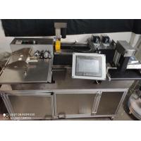
1.1 KP -G1
1.1.1 KP -G1 equipment appearance
Equipment Type: KP -G1 Category: Non-standard
Color: Silver Number :1
Overall Size :1200 mm*1000mm*1300mm Move Size :1500 mm*2000mm
Equipment reference picture:
1.1.2 KP -G1 Equipment Profile
KP -G1 equipment adopts computer all-digital control system,
convenient and simple, without too much operation, users can start
the equipment with one button, can be used. Mainly used for
multiple sheets of paper at the same time steel printing and nail,
can be stamped, can be embedded in the printer. The equipment
adopts modular design, mainly composed of transmission mechanism,
paper turning mechanism, seal mechanism and nail mounting
mechanism. The transmission mechanism is responsible for conveying
the paper from the printer and scanning the code to read the paper
information; the paper turning mechanism is responsible for
flipping, flattening and stacking the printed paper; the seal
mechanism is responsible for blocking the paper in a certain
position after flipping and stamping; The nail-binding mechanism is
responsible for pushing the stamped paper flat and pushing it into
the collection area. The whole process is fully automated, without
human operation, saving manpower and material resources.
1.1.3 KP -G1 technical parameters
Serial number | Parameter Name | Specific parameters |
1 | Control mode | Servo control |
2 | Paper size | A4 |
3 | Paper quantity | 1-4 sheets |
4 | Stamp Specification | Steel printing |
5 | Number of seals | 1 |
6 | Pin position | Long side |
7 | Number of nails | 2 |
8 | Overall dimensions | 1200 mm*1000mm*1300mm |
9 | Moving dimensions | 1500 mm*2000mm |
10 | Seal speed | mm/s 20-35 |
11 | Conveyor belt 1 speed | mm/s 25-45 |
12 | Conveyor belt 2 speed | mm/s 25-45 |
13 | Chapter Printing Current Position | cm 0 |
14 | Stamp Target Location | 40 cm |
15 | Paper spacing | cm 0 |
16 | Printing speed | ≤30/ min |
17 | Use of ambient temperature | 8-35℃ |
18 | Use of ambient relative humidity | Less than 80 per cent |
Note: factory system default setting, seal speed 25 mm/s; conveyor
belt 1 speed 35 mm/s; conveyor belt 2 speed 35 mm/s; steel printing
current position 0 cm; steel printing target position 40 paper
spacing 0 cm.
2.1 KP -G2
2.1.1 KP -G2 equipment appearance
Equipment Type: KP -G2 Category: Non-standard
Color: Silver Brown Quantity :1
Overall Size :1200 mm*500mm*930mm Move Size :2000 mm*1000mm
Equipment reference picture:
1.1.1 KP -G2 Equipment Profile
KP -G2 equipment adopts computer all-digital control system,
convenient and simple, without too much operation, users can start
the equipment with one button, can be used. Mainly used for sheet
paper front seal, can cover a chapter, not embedded in the printer.
The equipment adopts modular design, mainly composed of paper
dividing mechanism, transmission mechanism, seal mechanism and
three major mechanisms. The paper dividing mechanism is responsible
for separating the stacked paper from a single sheet; the
transmission mechanism is responsible for conveying the paper from
the paper dividing machine; the seal mechanism is responsible for
accurately sealing the single paper on the transmission mechanism;
Finally, the transmission mechanism is sent to the collection area.
The whole process realizes the stamp efficient and stable
automation, no human operation, save manpower.
1.1.2 KP -G2 technical parameters
Serial number | Parameter Name | Specific parameters |
1 | Control mode | Servo control |
2 | Paper size | A4 |
3 | Paper quantity | N sheet |
4 | Stamp Specification | Positive chapter |
5 | Number of seals | 1 |
6 | Pin position | No |
7 | Number of nails | No |
8 | Overall dimensions | 1200 mm*500mm*930mm |
9 | Moving dimensions | mm*1000mm 2000 |
10 | Seal speed | mm/s 20-35 |
11 | Conveyor belt 1 speed | mm/s 25-45 |
12 | Conveyor belt 2 speed | mm/s 25-45 |
13 | Chapter Printing Current Position | cm 0 |
14 | Stamp Target Location | 40 cm |
15 | Paper spacing | cm 0 |
16 | Printing speed | ≤30/ min |
17 | Use of ambient temperature | 8-35℃ |
18 | Use of ambient relative humidity | Less than 80 per cent |
Note: factory system default setting, seal speed 25 mm/s; conveyor
belt 1 speed 35 mm/s; conveyor belt 2 speed 35 mm/s; steel printing
current position 0 cm; steel printing target position 40 paper
spacing 0 cm.
1.1 KP -G3
1.1.1 KP -G3 equipment appearance
Equipment Type: KP -G3 Category: Non-standard
Color: Silver Number :1
Overall Size :1400 mm*700mm*1100mm Move Size :2400 mm*1500mm
Equipment reference picture:
1.1.2 KP -G3 Equipment Profile
KP -G3 equipment adopts computer all-digital control system,
convenient and simple, without too much operation, users can start
the equipment with one button, can be used. Mainly used for
multiple paper cover seams and nails, can cover two chapters, can
add cardboard package for the report, can not be embedded in the
printer. The equipment adopts modular design, mainly composed of
four mechanisms: paper separation mechanism, transmission
mechanism, seal mechanism and nail mounting mechanism. The paper
dividing mechanism is responsible for separating the stacked paper
from a single sheet; the transmission mechanism is responsible for
conveying the paper from the paper dividing machine; the seal
mechanism is divided into a cover seal and a cover seal. When the
face seal is sealed, the conveyor belt will transport the nailed
paper to the designated position, and then the seal mechanism will
carry out accurate seal; the nail mounting mechanism is responsible
for pushing the paper after the seal and pushing the conveyor belt
into the face seal.
2.2.3KP -G2 technical parameters
Serial number | Parameter Name | Specific parameters |
1 | Control mode | Servo control |
2 | Paper size | A4 |
3 | Paper quantity | N sheet |
4 | Stamp Specification | Seal, front seal |
5 | Number of seals | 2 |
6 | Pin position | Long side |
7 | Number of nails | 2 |
8 | Overall dimensions | 1400 mm*700mm*1100mm |
9 | Moving dimensions | mm*1500mm 2400 |
10 | Seal speed | mm/s 20-35 |
11 | Conveyor belt 1 speed | mm/s 25-45 |
12 | Conveyor belt 2 speed | mm/s 25-45 |
13 | Chapter Printing Current Position | cm 0 |
14 | Stamp Target Location | 40 cm |
15 | Paper spacing | cm 0 |
16 | Printing speed | ≤30/ min |
17 | Use of ambient temperature | 8-35℃ |
18 | Use of ambient relative humidity | Less than 80 per cent |
Note: factory system default setting, seal speed 25 mm/s; conveyor
belt 1 speed 35 mm/s; conveyor belt 2 speed 35 mm/s; steel printing
current position 0 cm; steel printing target position 40 paper
spacing 0 cm.
1. Design principles
Equipment in the design, integration, installation and
commissioning process mainly follow the following principles:
Always adhere to the principle of ensuring "four properties and
three advantages ", that is, system practicability, advanced
technology, system integration matching, long-term operation
reliability, as well as system equipment redundancy, fault
tolerance, expansion ability and upgrade ability.
Under the premise of ensuring the function of the system, the
famous brands and mature products at home and abroad are adopted to
match reasonably, optimize the performance and price ratio of the
system, and ensure the advanced nature and reliability of the
system.
Modular design is used to simplify the system structure, to
simplify installation, connection, disassembly and detection, and
to improve the maintainability of the system. In the design process
to minimize the connection link to reduce the occurrence of
accidents.
Using the popular software development platform, the man-machine
interface is friendly, the operation is simple, the maintenance,
the upgrade is convenient, the software function, the algorithm
module is universal, the applicability is strong, in the medium
supply, the system upgrade and so on certain expansion ability and
the interface.
Equipment design according to customer requirements and site
design, strive for simple structure, stable and reliable
installation, beautiful appearance, easy to move, easy to
disassemble.
Safety design: equipment design as far as possible to take measures
to reduce the risk and harm of equipment, to ensure the safety of
operators, equipment and systems.
Standardized design: under the premise of satisfying the function
and technical index, the system design gives priority to standard
parts and reduces non-standard equipment.
Priority is given to the selection of energy-saving products
recommended by the state to meet the requirements of energy
conservation.
4. functional features
1. The product uses servo electric cylinder to seal, the electric
cylinder has compact structure, light weight, good durability, high
energy efficiency and reliability, and the seal definition is
controllable and the precision is very high.
2. Stepper motor control conveyor belt to achieve accurate
positioning seal position and accurate dislocation stacking, and
speed precision adjustable.
3. Paper using conveyor belt stacking, can achieve multiple sheets
of paper at the same time seal nail, simple operation, convenient
and fast.
Small size, embedded printer equipment, can achieve automatic seal
nail, suitable for flexible use in the office. Can not be embedded
in printer equipment, separate a single paper from the paper
splitter, the paper is stable and fast, to achieve efficient seal
nail.
The servo control system can improve the reliability of the control
system, reduce the hardware cost of the controller, improve the
ability of information storage, monitoring, diagnosis and
hierarchical control, and make the servo system more intelligent.
The equipment installs the Fuma wheel, has the high bearing
capacity, can be used for the fixed support, also can realize the
roller movement, realizes the free movement equipment,.
Product performance is efficient and stable.
5. Composition and Principle of Equipment System
5.1 Composition of the equipment system
This product adopts profile frame structure, control system drives
servo cylinder, step motor, pneumatic push rod according to the
signal given by the controller.
● Main framework
● Composition: aluminum profile 304 stainless steel plate, sheet
metal shell.
● Role: responsible for supporting the stability of the whole
equipment system and the safety of equipment operation.
● Control box
● Composition: sheet metal box, electrical parts, servo controller.
● Role: distribution and control of equipment, in the circuit
overload, short circuit and leakage, but also provide power off
protection.
● Motion components
● Composition: servo cylinder, stepper motor, pneumatic push rod.
● Function: servo cylinder is responsible for sealing the report;
step motor is responsible for driving conveyor belt to transport A4
paper; pneumatic push rod is responsible for pushing, pushing and
pushing the paper with nails.
○ Main constituent bodies:
1. Transmission mechanism;
2. Stamp Agency:
3. Paper splitting mechanism;
4. Nailing mechanism;
5.1.1 Transmission mechanism
The transmission mechanism is mainly composed of conveyor belt and
stepping motor. Paper can be transmitted to ensure that the paper
smoothly into the next mechanism, conveyor belt installed with a
two-dimensional code scanner, can be used to identify how many
reports. It is convenient for the control system to make judgment
and carry out different control steps.
5.1.2 Stamping institutions
The seal mechanism is mainly composed of servo electric cylinder,
which can seal the paper on the conveyor belt. The clarity of the
seal is controlled by the control system and can be controlled by
the input parameters of the touch screen.
5.1.3 Paper splitting mechanism
The paper dividing mechanism is used on the non-embedded printer
equipment, which can separate the stacked paper and seal the paper
conveniently.
5.1.4 Nail mounting mechanism
The nail mounting mechanism consists of a paper hook, a pneumatic
push rod and an automatic nail mount. The report will enter the
nail area under the action of the transmission mechanism, the
pneumatic push rod will push the paper flat, the paper hook will
make the report enter the nail mount to realize the nail loading,
the nail is finished, and the pneumatic push rod will push the
report into the collection area.
5.2 Schematic diagram of the system
 Stepper motor drive signal
Figure 5-1 schematic diagram of the
system
5.3 Main components and characteristics of equipment system
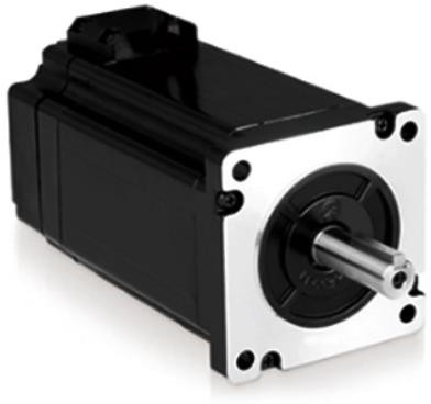
A. Stepper motor
The transmission mechanism of the equipment system is driven by
stepping motor, which is characterized by controlling the number of
pulses to control the angular displacement, so as to achieve the
purpose of accurate positioning. At the same time, the operation
process is relatively stable, low noise and low frequency
vibration.
Compared with DC motor, stepper motor has the following advantages:
1. the locking position, the motor no longer consumes electricity;
the stepper motor's unique "static torque "(also known as" holding
torque "," positioning torque ", etc.) has a certain locking torque
when the motor stops in a certain position.DC motor can also be
locked through the driver position, but the lock motor still
consumes electricity.2. small volume and long life; the life of
stepper motor usually depends on the bearing life, which can reach
tens of thousands to tens of thousands of hours, and the output
torque of stepper motor is larger than that of DC motor of equal
size.
Because it is open loop control and saves feedback devices such as
encoder, it not only simplifies the system composition, but also
reduces the cost effectively.
B. Servo cylinder
The seal mechanism of the equipment system adopts servo cylinder,
which is characterized by accurate speed control, accurate position
control and accurate thrust control.
Servo cylinder features: closed loop servo control, control
accuracy up to 0.01 mm; precision control thrust, increase pressure
sensor, control accuracy up to 1; easy to connect with PLC and
other control systems to achieve high precision motion control; low
noise, energy saving, Clean, high rigidity, impact resistance, long
life, simple operation and maintenance; can work for a long time,
and achieve high strength, high speed, high precision positioning,
smooth movement, low noise.
C. Pneumatic push rod
Pneumatic push rod is used to realize the automation of the nail
mounting mechanism on the equipment system, which is characterized
by simple component, small volume, quick action and quick reaction.
Can quickly achieve the report of the flat, nail.
D .PLC controller
 PLC controller is used in the control system of the equipment
system.PLC controller is a product that applies microelectronics
technology to industrial equipment. It has compact structure,
strong, small volume, light weight and low power consumption. And
PLC strong anti-interference ability, easy to load into the
equipment, is the ideal control equipment to achieve mechatronics.
PLC controller is used in the control system of the equipment
system.PLC controller is a product that applies microelectronics
technology to industrial equipment. It has compact structure,
strong, small volume, light weight and low power consumption. And
PLC strong anti-interference ability, easy to load into the
equipment, is the ideal control equipment to achieve mechatronics.
Data acquisition and processing: this PLC is responsible for the
acquisition of photoelectric sensor signals. Because the number of
papers reported is based on the counting feedback of photoelectric
sensors, and the control system sends out control signals to them.
Therefore, the system adopts high speed and high resolution PLC.,
which requires both signal acquisition accuracy and acquisition
speed
Switch input and output: PLC in the system as the input and output
center of all switches, avoid the complex circuit connection of
conventional logic circuit, and frequent replacement of
conventional circuit components; all logic protection functions are
completed inside the PLC. The system circuit diagram is simple and
clear.
E. other auxiliary electrical components
Auxiliary electrical components mainly include switching power
supply, relay, leakage protection switch, cable wire and
communication cable.
6. Safety Tips
6.1 Safety precautions for equipment use
1. Use the equipment in strict accordance with the equipment safety
operation process.
2. Safety inspection of the equipment before operation, after
determining the normal before use.
3. The safety protection device of mechanical equipment must be
used correctly according to the regulations.
Personal protective equipment must be properly worn. Long hair must
wear a work cap or tie up hair, must wear three tight (neckline
tight, cuff tight, pendulum tight) work clothes, can not wear
necklaces and other hanging objects, rotating equipment can not
wear gloves touch.
6. The metal case of all electrical equipment shall be well
grounded. No removal of earthing devices or any work on them is
allowed in use.
7. Signs on electrical equipment are not allowed to move except for
the original personnel or the responsible operator on duty.
8. Do not approach or contact any live part of electrical
equipment, special permission work, must do a good job of reliable
safety measures, and should comply with the relevant regulations.
9. Wet hands are not allowed to touch light switches and other
electrical equipment.
10. Power switch housing and cable, wire insulation must be
maintained in good condition, no use in case of defects..
11. If someone is electrocuted, the power supply should be cut off
first, so that the electric shock person is out of the power
supply, and first aid is carried out.
12. When the electrical equipment is on fire, the power supply of
the equipment should be cut off immediately and then put out the
fire. Dry type shall be used for electrical equipment that may be
charged, generators, motors, etc
Fire extinguishers, CO2 fire extinguishers, etc.; for oil circuit
breakers, transformers (isolated power supply) can use dry fire
extinguishers and other fire extinguishers, when can not be
extinguished with foam fire extinguishers, when forced to use dry
sand to extinguish fire; insulation oil on the ground fire, use dry
sand to extinguish fire..
13. When fighting a fire that may produce toxic gas (such as cable
fire), the fire extinguisher should use a positive pressure air
respirator.
14. Any electrical equipment shall be regarded as live equipment
before it is verified that there is no electricity.
15. Do not touch the moving parts during the operation of the
equipment to prevent danger.
6.2 Maintenance Safety Instructions
6.2.1 Mechanical aspects
When operating the equipment, be sure to refer to the instructions
manual.
Wear suitable overalls. Do not wear ties, necklaces or loose
clothes when operating or repairing equipment. Wear the necessary
protective devices. For example: gloves, no cap, goggles, etc.
Self-discipline and compliance with management arrangements.
Before operating the device, consider the steps of the operation.
Always stop all active parts before demonstrating any operation
next to the device.
6.2.2 Electrical aspects
The power supply and wiring end of the equipment always have
electrical hazards. In order to avoid any electric shock and death,
the main power supply should be cut off when maintaining the
equipment. And only qualified or trained maintenance personnel to
maintain and maintain equipment. Be sure to turn off the main power
supply before repairing the electrical line.
Please turn off the main power supply before any repair in the
electric box. Only trained personnel are allowed live maintenance
or adjustment.
Check and make sure the equipment / system is properly grounded.
General maintenance will not only ensure stable and reliable
operation, but also prolong the service life of the equipment.
Standard safety procedures should be strictly enforced when
performing any operation or repair of the equipment / system. This
can avoid any unnecessary accidents.
Understand and remember the location of all safety devices.