

Active Member
|
[China]

Address: NO.27,Jinlanling Street,Taigongling Village Dongguan 523829,Guangdong,China
Contact name:Eric

Aolittel Technology Co.,Ltd |
|
|
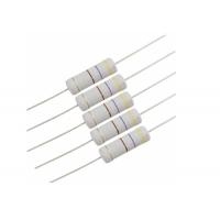
Miniaturized MOF Nonflammable Metal Oxide Film Resistor 470R 5W 700V 470 Ohm 2485 Gray Automatic Insertion
Features
● Miniaturized 50 % smaller compared to existing models
● Non-fl ammable
● High Reliability
● Automatic Insertion
● Reference Standards IEC 60115-2, IEC 60115-4, JIS C 5201-4, EIAJ RC-2138
● RoHS compliant
Scope
This specification is available for Metal Oxide Film Resistors manufactured by Aolittel Technology Co., Ltd.,it accords with RoHS test of Environment related substance requirement.

Type designation (example)
The type designation shall be in the following form and as specified.
MOF 1/4 W 10K J T52
MOF : Type- Metal Oxide Film Resistor
1/4W : Rated power
Normal Small
1/4W 1/2WS
1/2W 1WS
1W 2WS
2W 3WS
3W 5WS
5W
10K: Nominal resistance value E-24 Series E-96 Series
J: Resistancetolerance J ±5% G ±2% F ± 1%
T52:
Form
P Type
M Type
MB Type
FK1Type
FK2 Type
FKK Type
Rated power
Rated power is maximum power which can be continuously loaded at specified ambient temperature
70℃,as Table-1;however when the ambient temperature exceeds 70℃,rated power should be determined
from the derating curve .
Type
| Rated power
| Maximum working voltage | Maximum overload voltage | Dielectric withstanding voltage | Resistance Range(Ω) | |
| Normal size | MOF1/4W | 0.25W | 250V | 500V | 500V | 0.1Ω~100KΩ |
| MOF1/2W | 0.5W | 350V | 700V | 700V | 0.1Ω~100KΩ | |
| MOF1W | 1W | 500V | 800V | 900V | 0.1Ω~100KΩ | |
| MOF2W | 2W | 500V | 1000V | 1000V | 0.1Ω~100KΩ | |
| MOF3W | 3W | 500V | 1000V | 1000V | 0.1Ω~100KΩ | |
| MOF5W | 5W | 500V | 1000V | 1000V | 0.1Ω~100KΩ | |
| Small size | MOF1/2WS | 0.5W | 350V | 700V | 500V | 0.1Ω~100KΩ |
| MOF1WS | 1W | 350V | 800V | 700V | 0.1Ω~100KΩ | |
| MOF2WS | 2W | 500V | 1000V | 1000V | 0.1Ω~100KΩ | |
| MOF3WS | 3W | 500V | 1000V | 1000V | 0.1Ω~100KΩ | |
| MOF5WS | 5W | 500V | 1000V | 1000V | 0.1Ω~100KΩ | |
Structure diagram
The construction of resistor (MOF series) shall be as follows:

NO | Item | Material |
| 1 | Ceramic core | High alumina ceramic is used. |
| 2 | Resistor element | The resistor element shall consist of metal oxide film. |
| 3 | Terminal | Tinned iron cap. |
| 4 | Connection | The lead wire, which is plated with solder, shall be mounted to the caps by welding process. |
| 5 | Lead wire | Soldered or tinned annealed wire. |
| 6 | Finishing painting | Silicon resin is used. Accord with UL-94V-0 Nonflammable specification. |
| 7 | Indication | Color code. |
Resistor body color
| Normal size | Small size | ||
| Type | Color | Type | Color |
MOF1/4W,MOF1/2W, MOF1W,MOF2W, MOF3W,MOF5W | Gray | MOF1/2WS,MOF1WS, MOF2WS,MOF3WS, MOF5WS | Pink |
External dimensions
1) P Type

| Type | Dimensions | |||||
Normal Size | Small Size | I | L | ψD | ψd | H |
| MOF1/4W | MOF1/2WS | 60 | 6.5±0.5 | 2.3±0.5 | 0.45±0.05 | 28.0±2.0 |
| MOF1/2W | MOF1WS | 60 | 9.0±0.5 | 3.2±0.5 | 0.50±0.05 | 28.0±2.0 |
| MOF1W | MOF2WS | 60 | 11.5±1.0 | 4.5±0.5 | 0.7 0±0.05 | 25.0±2.0 |
| 81 | 11.5±1.0 | 4.5±0.5 | 0.7 0±0.05 | 35.0±2.0 | ||
| 94 | 11.5±1.0 | 4.5±0.5 | 0.7 0±0.05 | 42.0±2.0 | ||
| MOF2W | MOF3WS | 60 | 15.0±1.0 | 5.0±0.5 | 0.70±0.05 | 23.0±2.0 |
| 70 | 15.0±1.0 | 5.0±0.5 | 0.70±0.05 | 28±2.0 | ||
| 81 | 15.0±1.0 | 5.0±0.5 | 0.70±0.05 | 33.0±2.0 | ||
| 94 | 15.0±1.0 | 5.0±0.5 | 0.70±0.05 | 40.0±2.0 | ||
| MOF3W | MOF5WS | 81 | 17.5±1.0 | 6.0±0.5 | 0.70±0.05 | 38.0±2.0 |
| MOF5W | 94 | 24.5±1.0 | 8.0±0.5 | 0.70±0.05 | 35.0±2.0 | |
2) Axial Lead Taping--Txx Type
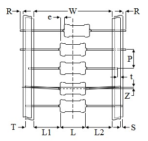
| Type | Taping | Dimensions | ||||||||||
Normal Size | Small Size | L | W | P | L1-L2 Max. | T | Z Max. | R Max. | t Max. | e Max. | S Max. | |
| MOF1/4W | MOF1/2WS | T26 | 6.0±0.5 | 26+1-0 | 5±0.5 | 0.5 | 6±0.5 | 1.2 | 0 | 3.0 | 0.6 | 0.5 |
| T52 | 6.0±0.5 | 52±1.0 | 5±0.5 | 1.0 | 6±0.5 | 1.2 | 0 | 3.0 | 0.6 | 0.5 | ||
| MOF1/2W | MOF1WS | T52 | 9.0±1.0 | 52±1.0 | 5±0.5 | 1.0 | 6±0.5 | 1.2 | 0 | 3.0 | 0.6 | 0.5 |
| MOF1W | MOF2WS | T52 | 11.0±1.0 | 52±1.0 | 5±0.5 | 1.0 | 6±0.5 | 1.2 | 0 | 3.0 | 0.6 | 0.5 |
| T73 | 11.0±1.0 | 73±1.0 | 5±0.5 | 1.0 | 6±0.5 | 1.2 | 0 | 3.0 | 0.6 | 0.5 | ||
| MOF2W | MOF3WS | T52 | 15.0±1.0 | 52±1.0 | 10±0.5 | 1.0 | 6±0.5 | 1.2 | 0 | 3.0 | 0.6 | 0.5 |
| T73 | 15.0±1.0 | 73±1.0 | 10±0.5 | 1.0 | 6±0.5 | 1.2 | 0 | 3.0 | 0.6 | 0.5 | ||
| T84 | 15.0±1.0 | 84±1.0 | 10±0.5 | 1.0 | 6±0.5 | 1.2 | 0 | 3.0 | 0.6 | 0.5 | ||
| MOF3W | MOF5WS | T84 | 17.5±1.5 | 84±1.0 | 10±0.5 | 1.0 | 6±0.5 | 1.2 | 0 | 3.0 | 0.6 | 0.5 |
| MOF5W | T84 | 24.5±1.5 | 84±1.0 | 10±0.5 | 1.0 | 6±0.5 | 1.2 | 0 | 3.0 | 0.6 | 0.5 | |
3) MB Type

Watts | Dimensions (mm) | |||||||
| D | L | P±1.0 | H1±1.0 | H2±0.5 | d±0.05 | t±0.15 | qMax | |
| 1/2w,1ws | 3.2±0.5 | 9.5±0.5 | 12.5/15 | 10.5 | 4.5 | 0.50 | 1.2 | 3 |
| 1w,2ws | 4.5±1.0 | 11.5±1.0 | 15 | 10.5 | 4.5 | 0.70 | 1.25 | 3 |
| 2w,3ws | 5.0±1.0 | 15.5±1.0 | 20 | 10.5 | 4.5 | 0.70 | 1.25 | 3 |
| 3W5WS | 6.0±1.0 | 17.5±1.0 | 25 | 10.5 | 4.5 | 0.70 | 1.25 | 3 |
| 5W | 8.0±1.0 | 24.5±1.0 | 30 | 10.5 | 4.5 | 0.70 | 1.25 | 3 |
4) M Type
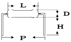
Watts | Dimensions (mm) | |||
| ΦD | L | P±1.0 | H±1.0 | |
| 1/8w,1/6w | 1.8±0.3 | 3.2±0.5 | 6 | 8 |
| 1/4w,1/2ws | 2.3±0.5 | 6.5±0.5 | 10 | 8 |
| 1/2w,1ws | 3.5±0.5 | 9.5±0.5 | 12.5/15 | 10 |
| 1w,2ws | 4.5±1.0 | 11.5±1.0 | 15 | 10 |
| 2w,3ws | 5.0±1.0 | 15.5±1.0 | 20 | 10 |
| 3w | 6.0±1.0 | 17.5±1.0 | 25 | 10 |
| 5w | 8.0±1.0 | 24.5±1.0 | 30 | 10 |
5)MK Type
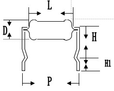
Watts | Dimensions (mm) | ||||
| D | L | P±1.0 | H±1.0 | H1±1.0 | |
| 1/2w,1ws | 3.2±0.5 | 9.5±0.5 | 12.5 | 10 | 4.5 |
| 1w,2ws | 4.5±1.0 | 11.5±1.0 | 15 | 10 | 4.5 |
| 2w,3ws | 5.0±1.0 | 15.5±1.0 | 20 | 10 | 4.5 |
| 3W5WS | 6.0±1.0 | 17.5±1.0 | 25 | 10 | 4.5 |
6) F Type
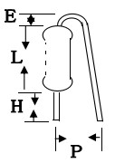
| Watts | Dimensions (mm) | ||||
| ΦD | L | P±2.0 | E Max | H±1.0 | |
| 1/2w,1ws | 3.2±0.5 | 9.5±0.5 | 6 | 3.5 | 5-8 |
| 1w,2ws | 4.5±1.0 | 11.5±1.0 | 8 | 3.5 | 5-8 |
| 2w,3ws | 5.0±1.0 | 15.5±1.0 | 8 | 3.5 | 5-8 |
| 3w | 6.0±1.0 | 17.5±1.0 | 8 | 3.5 | 5-8 |
7) FK2Type
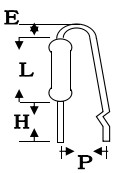
Watts | Dimensions (mm) | ||||
| ΦD | L | P±2.0 | E Max | H±1.0 | |
| 1/2w,1ws | 3.2±0.5 | 9.5±0.5 | 6 | 3.5 | 5-8 |
| 1w,2ws | 4.5±1.0 | 11.5±1.0 | 8 | 3.5 | 5-8 |
| 2w,3ws | 5.0±1.0 | 15.5±1.0 | 8 | 3.5 | 5-8 |
| 3w | 6.0±1.0 | 17.5±1.0 | 8 | 3.5 | 5-8 |
8)FKK Type

Watts | Dimensions(mm) | |||||
| ΦD | L | P±1.0 | E Max | H1±1.0 | H2±1.0 | |
| 1/2w,1ws | 3.2±0.5 | 9.5±0.5 | 5-7 | 3.5 | 8 | 4.5 |
| 1w,2ws | 4.5±1.0 | 11.5±1.0 | 5-9 | 3.5 | 8 | 4.5 |
| 2w,3ws | 5.0±1.0 | 15.5±1.0 | 5-9 | 3.5 | 8 | 4.5 |
| 3w | 6.0±1.0 | 17.5±1.0 | 5-10 | 3.5 | 8 | 4.5 |
Package
A.Tape in box packing (Ammo packing) Packing box size and quantity
| Type | Form | Quantity | Dimensions (mm) | |||
Normal Size | Small Size | L | W | H | ||
| MOF1/4W | MOF1/2WS | T26 | 5000 PCS | 260 | 50 | 100 |
| T52 | 5000 PCS | 260 | 80 | 100 | ||
| MOF1/2W | MOF1WS | T52 | 2000 PCS | 260 | 80 | 85 |
| MOF1W | MOF2WS | T52 | 1000 PCS | 260 | 80 | 85 |
| T73 | 1000 PCS | 260 | 95 | 92 | ||
| MOF2W | MOF3WS | T52 | 1000 PCS | 260 | 80 | 100 |
| T73 | 1000 PCS | 260 | 95 | 92 | ||
| MOF3W | MOF5WS | T84 | 500PCS | 260 | 110 | 75 |
| MOF5W | T84 | 250PCS | 260 | 110 | 75 | |
B. Tape in box Bulk (Ammo Bulk) Packing box size and quantity
| Type | Form | Quantity | Dimensions (mm) | |||
Normal Size | Small Size | L | W | H | ||
| MOF1/4W | MOF1/2WS | P | 10000 PCS | 240 | 140 | 76 |
| Moulding | 10000 PCS | 240 | 140 | 76 | ||
| MOF1/2W | MOF1WS | P | 5000 PCS | 240 | 140 | 76 |
| Moulding | 5000 PCS | 240 | 140 | 76 | ||
| MOF1W | MOF2WS | P | 2000 PCS | 240 | 140 | 76 |
| Moulding | 2000 PCS | 240 | 140 | 76 | ||
| MOF2W | MOF3WS | P | 2000 PCS | 240 | 140 | 76 |
| Moulding | 2000 PCS | 240 | 140 | 76 | ||
| MOF3W | MOF5WS | P | 100PCS | 240 | 140 | 76 |
| Moulding | 250PCS | 240 | 140 | 76 | ||
| MOF5W | P | 50PCS | 240 | 140 | 76 | |
| Moulding | 50PCS | 240 | 140 | 76 | ||
Factory View


Metal oxide film resistor definition
The metal oxide film resistor is a type of fixed resistor, which
uses metal oxide film as the resistive element to limit the flow of
electric current to certain level.
What is metal oxide?
Metal oxide is a metallic compound, which is formed because of the
chemical bonding between the oxygen atom and other elements.
Metallic compound consists of two or more different types of atoms
such as (tin with oxygen). In metal oxide film resistors, the film
is constructed by using the tin oxide.
What is tin oxide?
Tin oxide is a type of metallic compound, which is formed because
of the chemical bonding between the oxygen atom and tin.
Metal oxide film resistor construction
The construction of metal oxide film resistor is almost similar to
the metal film resistors. The main difference between the metal
oxide film resistor and the metal film resistor is material used
for constructing the film.
In metal film resistor, the film is constructed by using the metals such as nickel chromium whereas in metal oxide film resistors, the film is constructed by using the metal oxide such as tin oxide.
The metal oxide film resistor is made by coating the ceramic core with metal oxide such as tin oxide. The antimony oxide is added to the tin oxide to increase its resistivity. The resistivity of the metal oxide film is mainly depends on the amount of antimony oxide added to the tin oxide.

The film made of tin oxide and antimony oxide acts as the resistive element to the electric current. Hence, metal oxide film restricts the electric current to certain level. The ceramic core acts the insulating material to the electricity. Hence, the ceramic core does not allow heat through it. Thus, these resistors can withstand at high temperatures.
The metal end caps are fitted at both ends of the resistive element. The leads made of copper are joined at two ends of these metallic end caps. The metal oxide film resistors are able to withstand at higher temperatures than metal film and carbon film resistors.
In metal oxide film resistor, the desired resistance is achieved by cutting the metal oxide film in a helical manner along its length. Once the desired resistance value is achieved, the cutting of metal oxide film is stopped. Lasers are generally used to cut the metal oxide film in a helical manner.
Resistance of metal oxide film resistor is depends on the amount of
antimony oxide added, the thickness of metal oxide film layer, and
the width of helical metal oxide film cut
The resistance of the metal oxide film resistor is depends on the
amount of antimony oxide added to the tin oxide, the thickness of
the metal oxide film layer, and the width of helical metal oxide
film cut.


