|
|
[China]

Trade Verify
Contact name:Brunhilde Lung

Qingdao Jerryborg Marine Machinery Co., Ltd |
|
Verified Suppliers
|
|
|
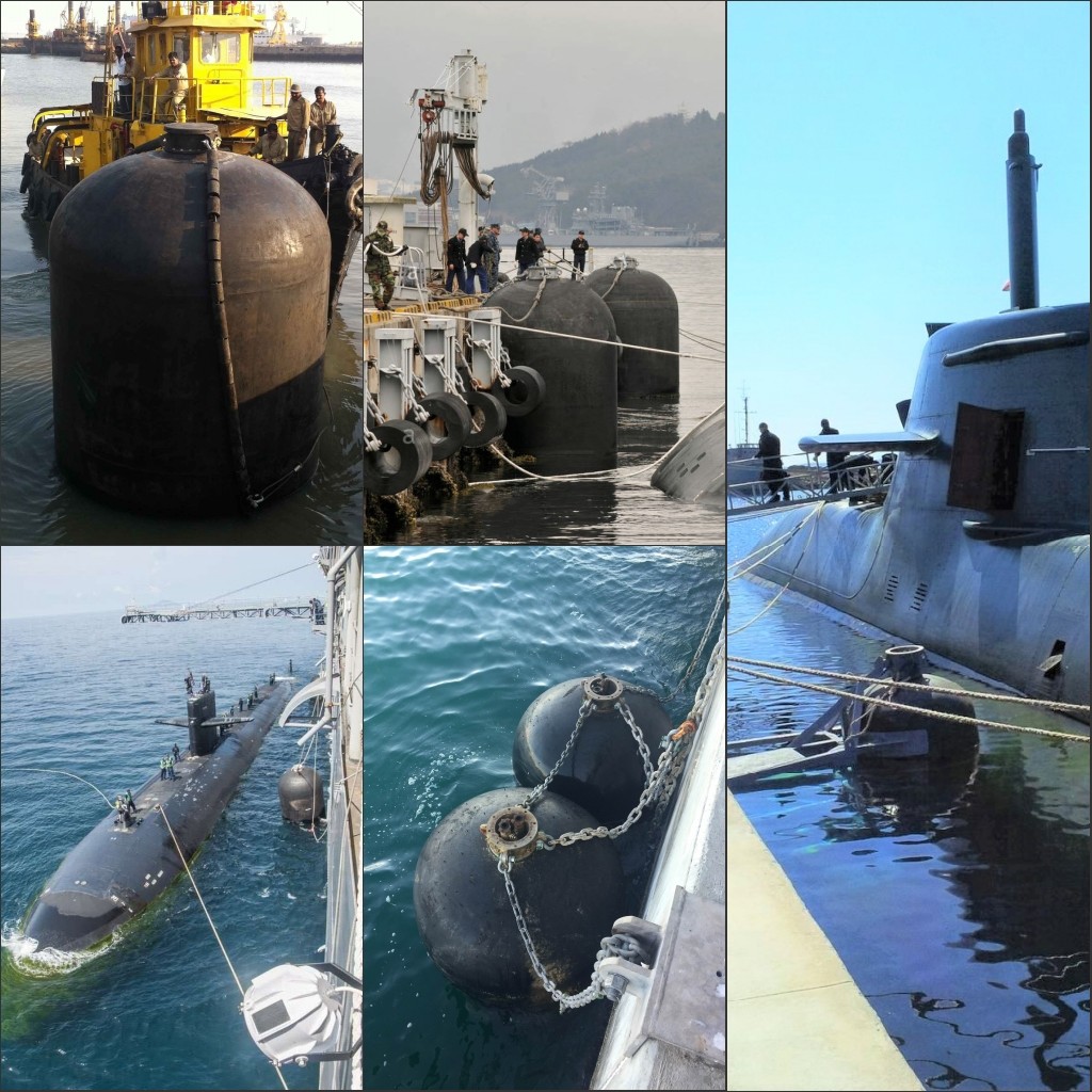
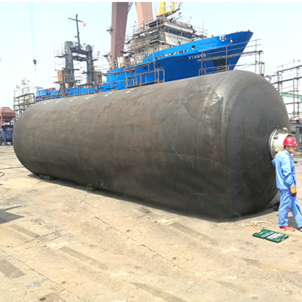
Hydropneumatic Fender Description
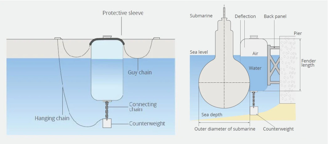
These Hydropneumatic Fenders are best employed for Submarines berthing application because of providing better contact surface vertically and adjustably. One of the most important criterias for using Yokohama hydropneumatic fender is high energy absorption capacity and low reaction force, which is vital factor for submarine applications.
Yokohama Hydropneumatic Fender is a special version of the
Pneumatic Fender developed for submarines. Hydropneumatic Fenders
are partially filled with water and air and are equipped with a
counterweight in order to keep them in a vertical position. This
ensures that the submerged hull is properly protected by the fender
at all times.
Yokohama Hydropneumatic Fender Advantages
1. Outstanding return on investment due to durable and long-lasting
material
2. Justified reassurance: rigorously tested, fully certified
products from long-established and globally recognised manufacturer
3. Low maintenance required as design withstands harsh marine
environments
4. Protects ships and mooring facilities even when excess load is
applied
5. Guaranteed reliability - consistent performance irrespective of
age or extreme temperatures
6. Suitable for various ship-to-quay and Ship-to-Ship applications
with different sizes available
7. Easy and inexpensive to install with only a guy rope or chain
required
8. Easily transferrable to alternative mooring points
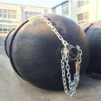
Hydro Pneumatic Fender Structure
1 .Outer rubber layer
Hydro pneumatic fenders are covered by the outer layer made of natural rubber. This rubber compound is strong enough to protect the inner layer and synthetic-cord layer from the damage of external forces and severe weather conditions due to its high elasticity and abrasion resistance.
2. Synthetic-tire-cord layer
The Synthetic-tire-cord layer is made of synthetic-tire-cord fabrics, compared with synthetic canvas fabric and synthetic belt fabric, this reinforcement layer performs better in fatigue-resistance and pressure-holding.
3. Inner rubber layer
The inner rubber layer is designed to seal the air inside the
fender.
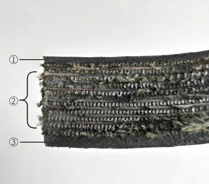
Hydropneumatic Fender Structure

Hydropneumatic Fender Technical Specifications
| Hydropneumatic Fender Size | Without water 60 % | Filled with water 45% | ||||
| Deflection | Deflection | |||||
| D x L | Reaction | Energy | Ratio Water | Reaction | Energy | |
| Force | Absorption | / Air | Force | Absorption | ||
| [mm] | [mm] | [kN] | [kNm] | [%] | [kN] | [kNm] |
| 1700 | 7200 | 1810 | 560 | 65/35 | 611 | 134 |
| 2000 | 6000 | 1766 | 647 | 65/35 | 599 | 155 |
| 2500 | 5500 | 2037 | 928 | 65/35 | 687 | 223 |
| 3300 | 6500 | 3169 | 1913 | 60/40 | 1247 | 616 |
| 3300 | 10600 | 5170 | 3120 | 55/45 | 1275 | 589 |
| * Other sizes can be customized according to the requirements. | ||||||
Hydropneumatic Fender Installation Cases
1. Navy base and submarine jetties
2. submarine and aircraft carrier docking operation
3. Certain ferry types
4. big floating pontoons
5. Oil Rigs