
|
|
[China]

Trade Verify
Address: Room 810, Unit 2, Building 5, Huixing Commercial Center, Dongsheng Road No.1, Zhongshan Dong, Shilong Town Dongguan, GUANGDONG, 523326 CN
Contact name:Anna

Guangdong Uchi Electronics Co.,Ltd |
|
Verified Suppliers
|
|
|
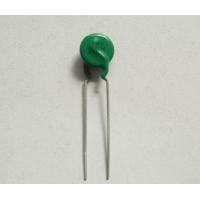
Smart PTC Thermistors Used For Energy-saving Lamps
Quick Details
1. Used in the frequent-switching,typical switching life can pass
over 100,000 times;
2. High reliability, good performance of safety and stability;
3. Wide operating temperature range;
-25 ~ +125℃(when V=0V)
0~ +60℃(when V=Vmax)
4. The withstanding voltage can reach to over 420-1000VAC;
5. The resistance will not drift in normal temperature.
6. Small dimension
7. Complete specifications
8. Stable delayed time
Description
ZD Smart PTC series is our patent product with the patent number of, mainly applied in the time-delay circuit of Electronic Ballasts and energy-saving lamp, to preheat the filament.
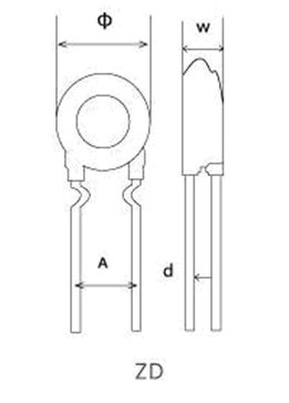
Model Number | Withstanding Voltage (V) | Voltage of the Tube applicable (Reference)(V) | Dimension(mm) | Wattage of the compact fluorescent Lamp Applicable (Reference) (W) | |||
Dmax | Tmax | A | d | ||||
ZD1-070906/048018 |
≥1000 | 45±5 |
9.5
|
7.5
|
5±1
|
0.6 | 7W lamps |
ZD1-070906/046016 | 60±5 | 9W,10 W Lamps | |||||
ZD1-071406/046016 | 90±10 | 11W,13 W Lamps | |||||
ZD1-071406/041025 | 90±10 | ||||||
ZD1-071456/047016 | 95±5 | 15W,18 W Lamps | |||||
ZD1-071506/043515 | 100±5 | ||||||
ZD1-071506/052014 | 105±5 | 20W,26W Lamps | |||||
ZD1-071505/062013 | 105±5 | ||||||
ZD1-071756/054014 | 105±5 | 20W,30W Lamps | |||||
ZD1-071756/057016 | 105±5 | ||||||
ZD1-070906/052014 | 60±5 | 18 W Electronic Ballasts | |||||
ZD1-071406/062013 | 85±5 | 30W Electronic Ballasts | |||||
ZD1-071505/052012 | 100±5 | 34W Electronic Ballasts | |||||
ZD1-101805/072013 | 105±5 |
12.5 |
7.8 |
7.5±1 |
0.75 | 36W,40W Electronic Ballasts | |
ZD1-102055/055012 | 165±5 | T5 28W Electronic Ballasts | |||||
ZD1-102255/052512 | 165±5 | T5 28W Electronic Ballasts | |||||
Note: If not specified, Resistance @25C (R25) tolerance shall be +/-25%.
Reference information in selecting PTC thermistor over-current protection devices for overcurrent and overload protection.
1) Maximum operating voltage
PTC Thermistor over-current protection device is connected in
series in the circuit , In normal operating state, only a small
portion voltage is on PTC thermistor protector. When PTC thermistor
current limiting devices is in high resistance state, it must bear
almost all the power voltage. Therefore in PTC thermistor protector
model selection, it must have sufficient high operating voltage,
and also power voltage fluctuation must be taken into
consideration.
2) Rated current ( Non-trip current) and Switching current (Trip current)
The PTC thermistor over-current protection device should have
sufficient high rated current (that current at which the PTC
thermistor protector will under no circumstances turn off) within
the suitable voltage class. Consider whether the overall layout of
the circuit can handle the increased power for the short time until
the PTC thermistor protector reduces it. Here a worst case estimate
is necessary. Rated current ( Non-trip current) and Switching
current (Trip current) depend on the ambient temperature. So, as
the worst case for the rated current, the maximum permissible
temperature for the application should be taken, and for the
switching current the lowest possible ambient temperature. In order
to get reliable switching function, tripping current should be at
least twice of non-trip current.
3) Maximum current permissible in maximum operating voltage
When PTC Thermistor over-current protection device is required for
protective function, it needs to check whether there is the case
that the maximum permissible current, which has been listed in data
sheet, has been exceeded. Overloading the PTC thermistor protector
by too high a switching current must be avoided, it may lead to PTC
thermistor protector destroyed, or early failure.
4)Selection of Reference temperature (also called Switch
temperature or Curie temperature)
We can offer PTC thermistor for over-current protection with
reference temperature 80 ℃, 100 ℃, 120 ℃, 140 ℃. The rated current
(non-trip current) depends on reference temperature and ceramic
body diameter. In consideration of cutting down cost, high
reference temperature and small dimension PTC Thermistor current
limiting devices shall be more economical, but it may leads to
higher PTC thermistor surface temperature, and need to check
whether it will cause undesired unfavorable effects. Generally,
reference temperature should be 20--40 ℃ higher than maximum
operating ambient temperature.
5) Application environmental effects
If there is any contact with chemicals or use of potting or sealing
compounds, all due care should be taken. The reduction of the
titanate ceramic that can be caused by chemical effects on the
surface of the thermistor and the resulting formation of
low-resistance conducting paths. And the altered thermal relations
in the sealant can lead to local overheating of the PTC thermistor
protector and thus to failure.
An example of PTC thermistor over-current protection devices part
selection for overload protection of power transformer.
An transformer has primary voltage 220V, secondary voltage 16V,
secondary current 1.5A , primary current 330mA in abnormal
condition, it shall enter into protective state within 10 minutes.
Operating ambient temperature: -10C--+40C , temperature may rise
15--20C in normal operating state. PTC Thermistor will be installed
near transformer. Please select an appropriate PTC thermistor part
for primary protection.
1) Determine maximum operating voltage
Operating voltage 220V, considering power fluctuation, maximum
operating voltage should be
220V x (1+20% ) =264V
Maximum operating voltage shall be 265V.
2) Determine non-trip current
According to calculation and actual measurement, primary current is
125mA in transformer normal operation. In consideration the ambient
temperature in installation position may reach to 60℃ , Non-trip
current in 60℃ should be 130--140mA.
3) Determine trip current
As the ambient temperature in PTC thermistor protector installation
position may reach -10 ℃ , non trip current in -10 ℃ should be
320-330mA, tripping time within 5 minutes.
4) Determine rated zero power resistance at 25 centigrade. R25
PTC thermistor is in series in the primary circuit, the voltage
decreasing should be possibly small, the heating power of PTC
Thermistor itself also maintain possibly small. Generally, the
voltage decreasing should be less than total power voltage 1%. We
can get R25 through calculation
220V X 1% ÷125mA=17.6Ω
5) Determine maximum current
Trough practical measurement, primary current can reach 500mA in
transformer secondary circuit in short circuit state. If
considering that larger current may pass through PTC thermistor in
the state of primary coil partial short circuit. The maximum
current should be more than 1A .
6) Determine reference temperature and dimension of PTC thermistor
over-current protection device
Maximum ambient temperature in PTC thermistor protector
installation position may reach 60 ℃ , reference temperature should
be 40 ℃ higher than that, then the reference temperature can be 100
℃ . In considering cutting down cost, also PTC thermistor is not
installed in the transformer windings coil, higher surface
temperature won't have unfavorable effect to transformer, therefore
reference temperature can also be 120 ℃ , and then the diameter of
PTC Thermistor can be smaller.
7) Determine PTC thermistor over-current protection device part
number.
Based on the above technical requirement, in reference of our
technical data, AMZ11-10P15RH265 shall be more appropriate.
Maximum operating voltage 265V, rated zero power resistance at 25C
(R25) 15 Ω±20% , non-trip current 140mA , trip current 350 mA ,
maximum current 1.5A , reference temperature 120 ℃ , diameter 11mm
.
Competitive Advantage:,
Factory supply directly
Completed certificates such as UL,VDE,SGS,etc and high quality available
Quick delivery
Best after-sales services
OEM & ODM available


